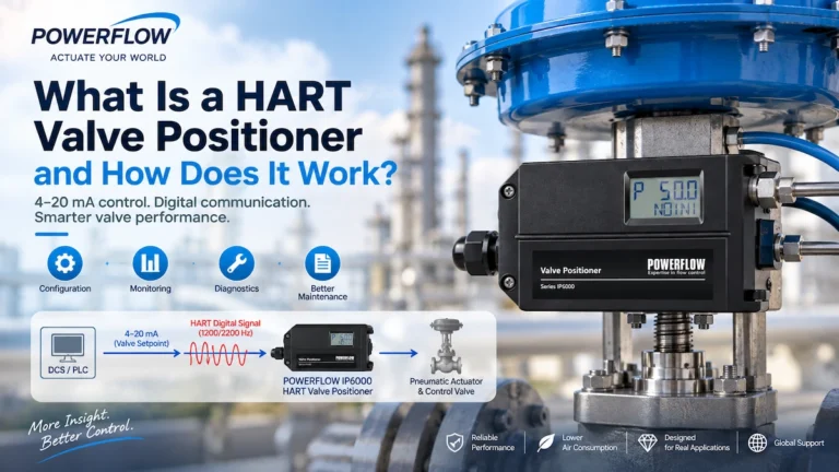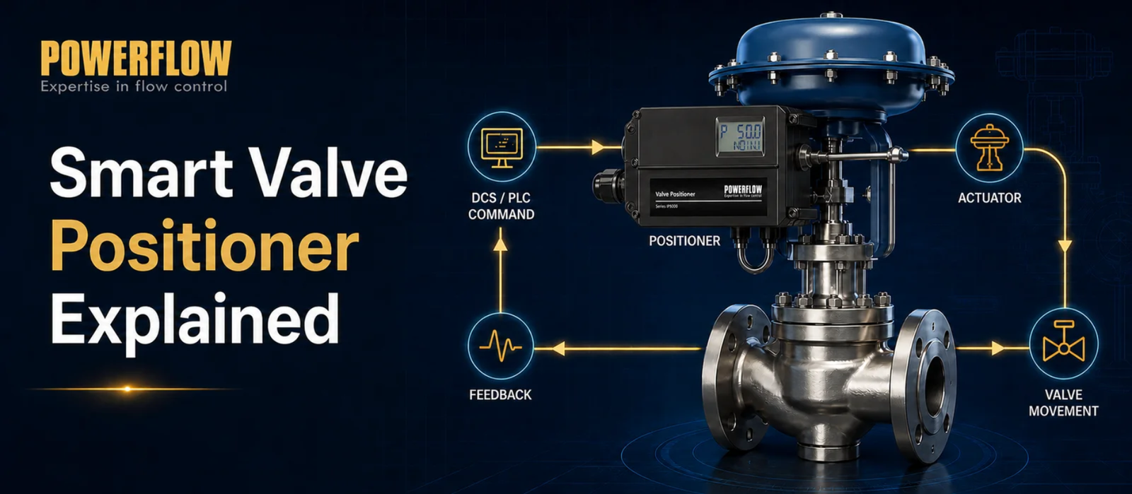
A smart valve positioner is a digital electro-pneumatic device that controls the position of a pneumatic control valve. It receives a command signal—typically 4–20 mA—from a DCS or PLC, compares the requested valve position with the actual position, and adjusts the pneumatic output to the actuator until the valve reaches the target position.
Unlike conventional pneumatic or analog positioners, smart valve positioners use a microprocessor and position feedback sensor. Depending on the model, they may also provide automatic calibration, diagnostics, position monitoring, HART communication, or digital fieldbus communication.
This guide explains how a smart valve positioner works, its main components and benefits, where it is used, and what to consider when selecting one.
What Is a Smart Valve Positioner?
A smart valve positioner is installed on a pneumatic control valve to ensure that the valve reaches and maintains the position requested by the process control system.
The positioner receives a command from a DCS or PLC and measures the actual position of the valve stem or rotary shaft. If the requested and actual positions do not match, it changes the pneumatic pressure supplied to the actuator. The actuator then moves the valve in the required direction.
This creates a closed-loop valve position control system.
Compared with conventional valve positioners, smart positioners incorporate digital electronics and a microprocessor. This enables functions such as automatic initialization, parameter configuration, status monitoring, and diagnostics, although the exact capabilities depend on the product model and communication protocol.
How Does a Smart Valve Positioner Work?
The working principle of a smart valve positioner is based on closed-loop feedback control:
Control signal → Smart positioner → Pneumatic output → Actuator → Valve movement → Position feedback
The positioner continuously compares the requested valve position with the actual position and corrects any deviation.
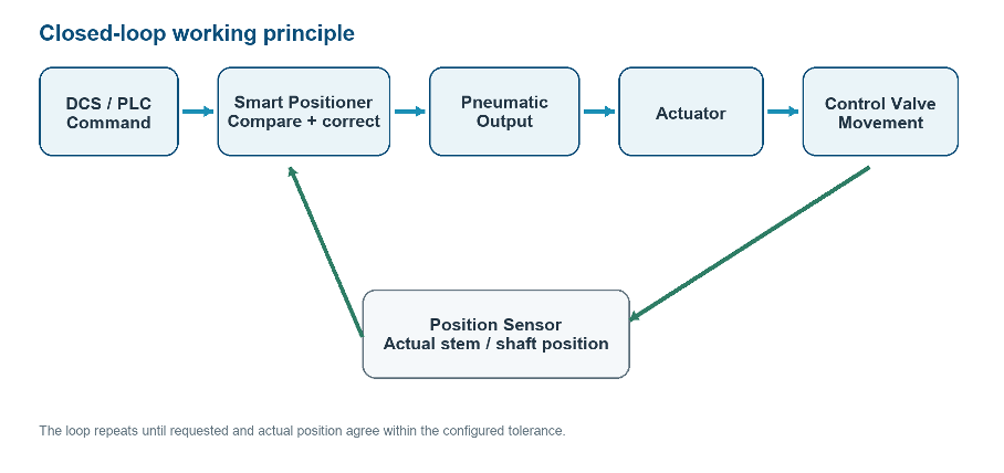 Figure 1. Smart valve positioner closed-loop working principle.
1. Control Signal Input
The smart valve positioner receives a control command from a DCS, PLC, or another process control system.
A common input is a 4–20 mA analog signal. Depending on the configured valve action, 4 mA may represent one end of the valve travel and 20 mA the other.
Some models also support digital communication. For example, HART communication adds digital information to a conventional 4–20 mA loop, while PROFIBUS PA provides digital fieldbus communication for compatible process automation systems.
For a deeper explanation of HART communication, see our guide to HART valve positioners.
2. Valve Position Measurement
A built-in position sensor measures the actual movement of the valve stem or rotary shaft.
Depending on the positioner design, the sensor may use a mechanical linkage, potentiometer, magnetic sensor, or another sensing technology.
3. Microprocessor Comparison
The internal microprocessor compares:
Requested valve position vs. actual valve position
If a deviation exists, the positioner calculates the correction required to move the valve closer to the requested position.
4. Pneumatic Output Adjustment
The positioner regulates the pneumatic output supplied to the actuator. The actuator converts this pressure into mechanical movement and moves the valve stem or shaft.
The pneumatic output configuration must match the actuator type. A single-acting actuator normally uses air pressure in one direction and a spring for the return movement, while a double-acting actuator requires pneumatic control in both directions.
5. Position Correction
The position sensor measures the valve position again and sends updated information to the microprocessor.
This feedback loop continues until the actual position matches the requested position within the configured control tolerance.
Closed-loop control can help reduce the effects of valve friction, mechanical hysteresis, changing process forces, and pneumatic supply variations. It does not eliminate these factors completely, but it can improve positioning stability and repeatability.
Main Components of a Smart Valve Positioner
The internal design varies between manufacturers and models, but most smart valve positioners contain the following functional components:
| Component | Main function |
|---|---|
| Microprocessor | Processes the command signal and calculates valve position corrections |
| Position sensor | Measures the actual valve stem or shaft position |
| Electro-pneumatic control system | Regulates pneumatic output to the actuator |
| Communication interface | Supports configuration, monitoring, and communication |
| Local display and controls | Enables local commissioning and status checks, depending on the model |
These components allow the positioner to combine electronic signal processing with pneumatic actuator control.
Smart Valve Positioner vs. Conventional Valve Positioner
Both smart and conventional valve positioners perform the same basic task: moving a valve according to a control command. The main difference is how the control is performed and what additional functions are available.
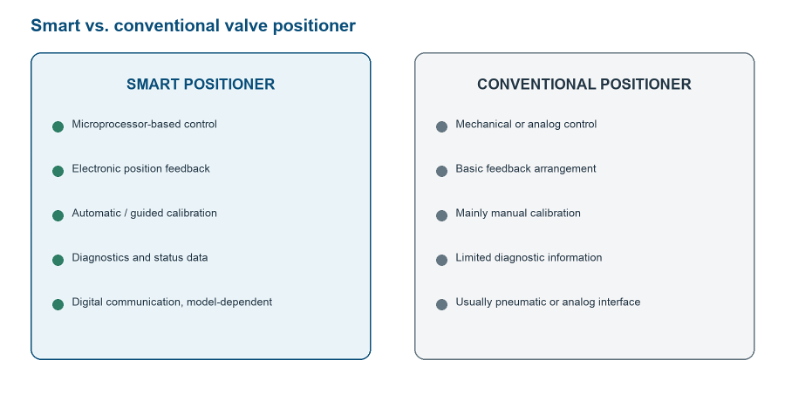 Figure 2. Functional comparison of smart and conventional valve positioners.
| Feature | Smart valve positioner | Conventional valve positioner |
|---|---|---|
| Control technology | Microprocessor-based digital control | Mechanical, pneumatic, or analog control |
| Position feedback | Continuous electronic feedback | Basic mechanical or analog feedback |
| Calibration | Automatic or guided calibration may be available | Mainly manual |
| Diagnostics | Available depending on the model | Limited |
| Configuration | Digital parameter configuration | Mainly manual adjustment |
| Communication | 4–20 mA, HART, or fieldbus depending on the model | Usually pneumatic or analog |
| Maintenance support | Status and diagnostic data may assist maintenance | Mainly manual inspection |
A conventional positioner may still be sufficient when an application requires only basic valve positioning.
A smart valve positioner is more appropriate when the application requires automatic calibration, digital configuration, diagnostics, communication, or access to valve status information.
Key Benefits of Smart Valve Positioners
Improved Positioning Accuracy and Repeatability
Smart valve positioners use digital signal processing and continuous position feedback to regulate actuator movement.
By comparing the requested position with the actual valve position, the positioner can correct deviations and reduce the effects of friction, hysteresis, and changing process forces. Actual positioning performance still depends on the positioner, actuator, valve assembly, installation quality, and operating conditions.
Automatic Calibration
Many smart positioners provide automatic initialization or calibration.
During commissioning, the positioner may identify parameters such as valve travel, rotation range, and actuator behavior. It then configures its control response accordingly.
This can reduce manual adjustment and simplify commissioning, but the procedure must still follow the applicable product and installation instructions.
Diagnostics and Monitoring
Depending on the model, a smart valve positioner may monitor operating conditions and provide diagnostic information related to:
- Position deviation
- Restricted valve movement
- Excessive friction
- Pneumatic supply problems
- Signal abnormalities
- Changes in valve or actuator performance
- Excessive accumulated travel
- Abnormal response time
Diagnostic information can help maintenance teams identify developing problems before they cause significant process disturbances. Exact diagnostic functions must always be confirmed in the relevant product documentation.
Digital Communication
Communication protocols such as HART and PROFIBUS PA can provide access to more information than a basic analog loop alone.
Depending on the system architecture and positioner model, operators may be able to access configuration parameters, actual valve position, device status, alarms, and diagnostic data.
Easier Commissioning and Maintenance
Automatic calibration, digital configuration, and diagnostic information can reduce the manual work required during commissioning and routine maintenance.
Instead of relying entirely on physical inspection, maintenance teams can use available device data to investigate potential valve or actuator problems and plan maintenance more efficiently.
Where Are Smart Valve Positioners Used?
Smart valve positioners are used wherever pneumatic control valves require accurate, repeatable, and automated positioning.
Typical industries include:
- Oil and gas: Flow, pressure, level, and temperature control in pipelines, refineries, and gas-processing facilities.
- Chemical processing: Control of process media under demanding operating and environmental conditions.
- Power generation: Steam, water, fuel, condensate, cooling, and auxiliary control systems.
- Food and beverage: Repeatable process-fluid control in mixing, dosing, and automated production.
- Water and wastewater treatment: Water supply, chemical dosing, filtration, and automated flow control.
- Metallurgy and steel: Control-valve applications operating under demanding industrial conditions.
For hazardous locations, the selected positioner must meet the applicable explosion-protection and installation requirements.
How to Choose a Smart Valve Positioner
Selecting a smart valve positioner requires more than checking the input signal. The positioner must match the valve, actuator, control system, installation environment, and required functions.
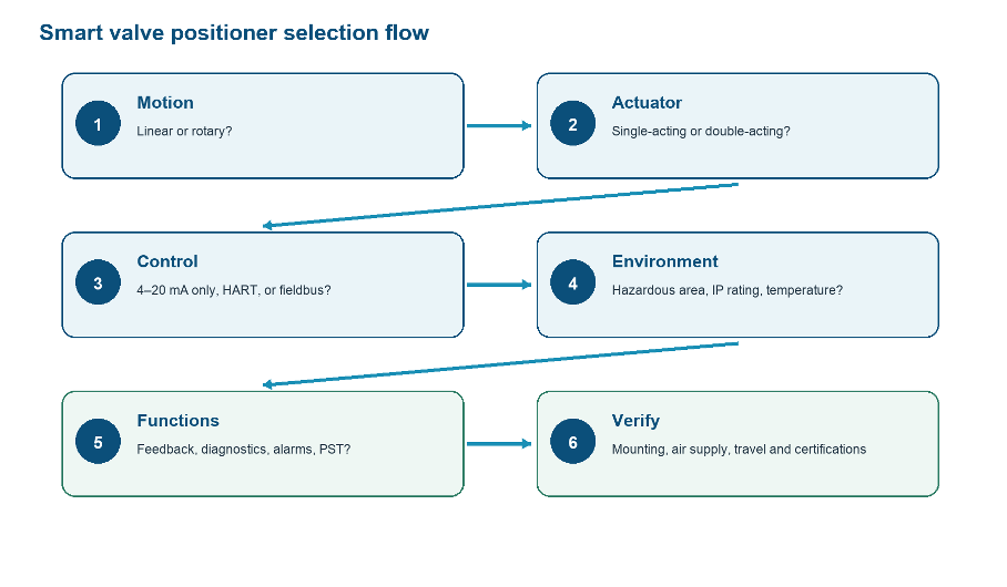
Figure 3. Smart valve positioner selection checklist.
| Selection factor | What to confirm |
|---|---|
| Valve motion | Linear or rotary |
| Actuator type | Single-acting or double-acting |
| Control signal | Commonly 4–20 mA |
| Communication | HART, PROFIBUS PA, or another required protocol |
| Hazardous area | Required protection concept, zone, gas or dust group, and certification |
| Environmental conditions | Dust, rain, humidity, washdown, corrosion, and IP rating |
| Pneumatic supply | Pressure range, air quality, connections, and output capacity |
| Operating temperature | Permitted ambient-temperature range |
| Required functions | Feedback, alarms, diagnostics, local display, and remote configuration |
Valve and Actuator Compatibility
Determine whether the valve uses linear or rotary motion and whether the actuator is single-acting or double-acting.
The mounting method, travel or rotation range, pneumatic outputs, and feedback mechanism must all be compatible with the valve and actuator.
Signal and Communication Requirements
Confirm the control architecture used by the plant:
- 4–20 mA provides a conventional analog position command.
- HART combines digital communication with a 4–20 mA loop.
- PROFIBUS PA provides digital fieldbus communication for compatible process automation networks.
For an example of a POWERFLOW model with smart communication options, see the POWERFLOW IP7000 non-contact smart valve positioner.
For applications requiring PROFIBUS PA, see the POWERFLOW IP6500 PROFIBUS PA smart valve positioner.
Pneumatic and Functional Requirements
Confirm the available instrument-air pressure and quality, pneumatic connection size, output capacity, actuator volume, and required stroking speed.
Also determine whether the application requires position feedback, alarm outputs, a local display, remote configuration, advanced diagnostics, or partial-stroke testing. Not every application requires every available function.
IP Ratings and Certifications
Environmental Protection and IP Ratings
The required enclosure protection rating depends on the actual installation environment.
Common ratings for industrial valve positioners may include:
| Rating | General meaning |
|---|---|
| IP65 | Dust protection and protection against water jets under specified test conditions |
| IP67 | Dust protection and temporary water immersion under specified test conditions |
| IP69K / IPX9 | Protection against high-pressure, high-temperature water jets under specified test conditions |
IP69K originated from DIN 40050-9, while the corresponding high-pressure and high-temperature water-jet test is identified as IPX9 in the current IEC 60529 classification. Terminology may therefore depend on the applicable standard and certificate.
Learn more about IP69K and IPX9 classifications.
An IP rating does not automatically mean that a device is suitable for every washdown, immersion, chemical-cleaning, or outdoor application. The rating applies only when the device is installed according to the manufacturer’s instructions, including the specified seals, covers, cable glands, mounting orientation, and operating conditions.
Hazardous-Area and Functional-Safety Certifications
Smart valve positioners used in hazardous areas may require certification or documentation such as ATEX, IECEx, EAC, CE, or functional-safety documentation.
Before selecting a positioner, confirm:
- The exact model and hardware version
- Protection concept, such as Ex i or Ex d
- Gas or dust group
- Equipment protection level or zone
- Temperature class and ambient-temperature range
- Certificate number and scope
- Cable-entry and grounding requirements
- Special conditions of use
A general statement that a product is “explosion-proof” is not sufficient for model selection. Certification coverage varies by model, configuration, optional module, and production version.
Likewise, SIL-related documentation does not mean that every installation automatically achieves a particular SIL level. The positioner must be evaluated as part of the complete safety instrumented function.
Review the available POWERFLOW certifications and compliance documents and confirm the applicable datasheet, certificate, installation manual, and safety manual before making a final selection.
Frequently Asked Questions About Smart Valve Positioners
What does a smart valve positioner do?
A smart valve positioner controls the position of a pneumatic control valve. It compares the position requested by the control system with the actual valve position and adjusts pneumatic pressure to the actuator to correct any difference.
What signal does a smart valve positioner use?
Many smart valve positioners use a 4–20 mA input signal. Depending on the model, HART, PROFIBUS PA, or another digital communication option may also be available.
What is the difference between a smart and conventional valve positioner?
A conventional positioner controls valve movement using pneumatic, mechanical, or analog mechanisms. A smart positioner adds microprocessor-based control, electronic feedback, digital configuration, and—depending on the model—diagnostics and communication.
Can a smart valve positioner be used with linear and rotary valves?
Yes. Smart valve positioners are available for linear and rotary applications. However, the mounting hardware, travel or rotation range, actuator configuration, pneumatic outputs, and feedback mechanism must match the specific valve and actuator.
Is a smart valve positioner the same as an I/P converter?
No. An I/P converter primarily converts an electrical current signal into pneumatic pressure.
A smart valve positioner also measures the actual valve position and uses closed-loop feedback to adjust actuator pressure until the requested valve position is achieved.
Is a Smart Valve Positioner the Same as a Digital or Intelligent Valve Positioner?
Yes. In industrial process control, the terms smart valve positioner, digital valve positioner, and intelligent valve positioner are commonly used to describe the same general category of microprocessor-based valve positioners. Different manufacturers may use different terminology, but the basic operating principle is generally the same. When selecting a positioner, users should compare the actual functions and specifications rather than relying only on the product name.
POWERFLOW Smart Valve Positioners
POWERFLOW provides smart valve positioners for linear and rotary valves, single-acting and double-acting actuators, conventional 4–20 mA control, and digital communication applications.
Depending on the selected model, available options may include automatic calibration, position feedback, a local display, diagnostics, HART communication, PROFIBUS PA, hazardous-area configurations, and different enclosure protection ratings.
The correct model should be selected according to the valve and actuator type, control architecture, pneumatic supply, environmental conditions, and applicable certification requirements.
Explore POWERFLOW smart valve positioners or contact POWERFLOW for model-selection support.
Conclusion
A smart valve positioner combines closed-loop valve position control with microprocessor-based digital technology. It continuously compares the requested valve position with the actual position and adjusts pneumatic output to the actuator.
Compared with conventional positioners, smart models may also provide automatic calibration, digital configuration, diagnostics, position monitoring, and communication.
When selecting a positioner, consider the valve and actuator type, control signal, communication protocol, pneumatic requirements, hazardous-area classification, IP rating, operating temperature, and required diagnostic functions. Always confirm specifications and certification coverage using the documentation for the exact product model.