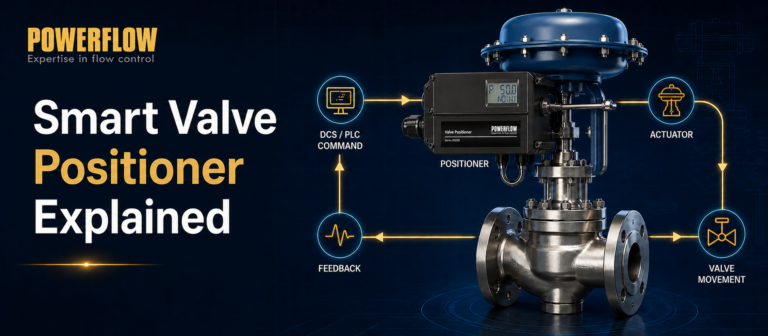
“4–20 mA + HART” has become a common requirement in control valve specifications. However, HART is often misunderstood. Some users see it as a more advanced control signal, while others assume that adding HART automatically means the valve can be remotely controlled.
In a typical point-to-point HART valve positioner application, the 4–20 mA signal carries the valve position setpoint, while HART adds a bidirectional digital communication channel to the same pair of wires. This allows engineers and maintenance teams to configure the positioner, read valve status, perform calibration, and access diagnostic information.
So what exactly does HART add to a smart valve positioner—and when is it actually worth using?
This guide explains how a HART valve positioner works, how HART communication coexists with the 4–20 mA signal, what it can and cannot do, and what to consider when selecting one.
What Is a HART Valve Positioner?
A HART valve positioner is a smart electro-pneumatic valve positioner that combines conventional 4–20 mA valve control with HART (Highway Addressable Remote Transducer) digital communication.
In a typical point-to-point installation, the 4–20 mA signal tells the positioner where the valve should move. For example, depending on the configured action:
- 4 mA may represent 0% valve position.
- 12 mA may represent approximately 50%.
- 20 mA may represent 100%.
HART does not replace this analog control signal. Instead, it provides a bidirectional digital data channel superimposed on the same 4–20 mA loop.
Through HART communication, compatible host systems or handheld communicators can access functions such as parameter configuration, valve status, calibration, alarms, and diagnostic information without requiring a separate communication cable.
Is Every Smart Valve Positioner a HART Positioner?
No.
“Smart” and “HART” are related, but they are not the same thing.
A smart valve positioner may use a microprocessor, position sensor, automatic calibration, local configuration, and position feedback without supporting HART communication.
HART adds the ability to communicate digitally with the positioner from a compatible host device or control system.
For example, POWERFLOW's 1500, 1600/1601, and 1880S series are smart positioners but do not support HART. HART communication is available on selected models including the IP6000, IP6000d, and IP7000, subject to model and configuration.
How Does a HART Valve Positioner Work?
The valve positioning process itself is based on closed-loop position control.
The basic control path is:
DCS/PLC → 4–20 mA Setpoint → Valve Positioner → Pneumatic Actuator → Control Valve → Position Feedback
The DCS or PLC sends a 4–20 mA setpoint to the positioner. The positioner converts this signal into a target valve position and compares it with the actual position measured by its position sensor.
If there is a deviation, the internal microprocessor controls the pneumatic output stage to increase or decrease actuator pressure. The actuator moves the valve stem or shaft, and the new valve position is measured again.
This process continuously repeats to keep the actual valve position within the required control tolerance.
Where Does HART Fit Into This Process?
In a conventional point-to-point HART installation, HART does not replace the 4–20 mA setpoint used for normal valve positioning.
Instead, it operates as a separate digital communication layer on the same two wires.
4–20 mA tells the valve where to go. HART tells you what is happening inside the positioner.
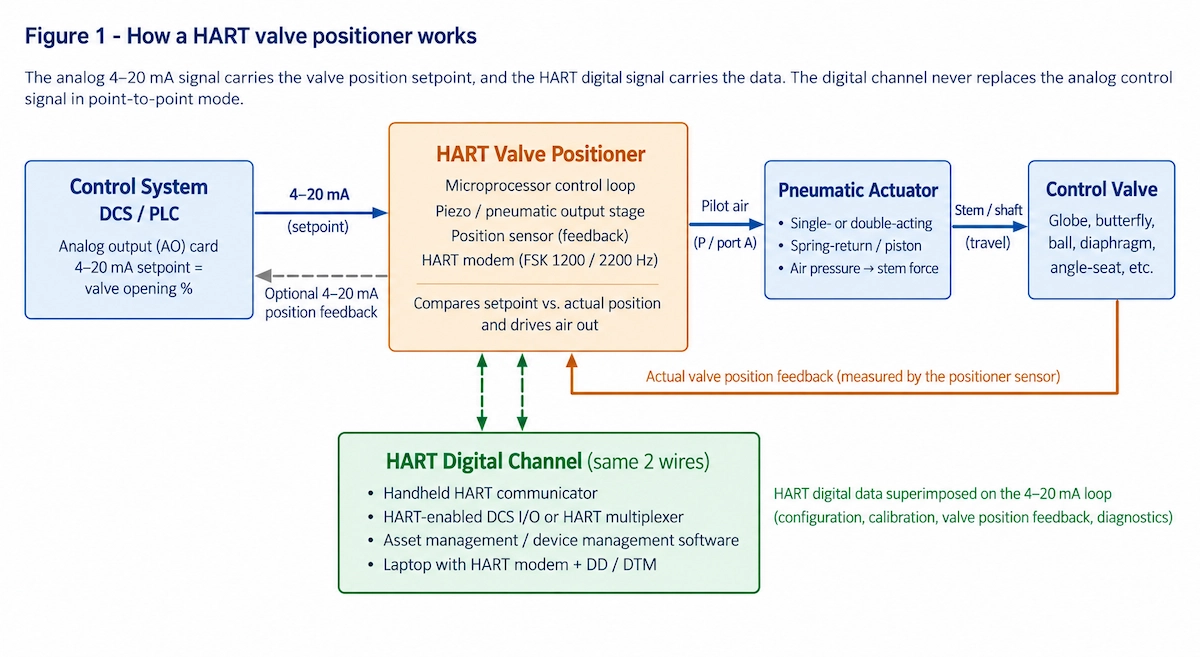
Figure 1. How a HART valve positioner uses 4–20 mA for the valve setpoint and HART for digital device communication.
How Is HART Superimposed on a 4–20 mA Signal?
According to FieldComm Group's explanation of HART technology, HART communication uses Frequency Shift Keying (FSK) based on the Bell 202 standard.
A small AC signal is superimposed on the 4–20 mA DC current loop:
- 1200 Hz represents digital logic 1.
- 2200 Hz represents digital logic 0.
- The communication rate is 1200 bit/s.
Because the average value of the FSK signal is zero, it does not change the DC average value of the 4–20 mA control signal.
This allows the analog control signal and HART digital communication to coexist on the same pair of wires.
The relatively low HART communication bandwidth is suitable for device configuration, status monitoring, and diagnostics, but it is not intended to replace the real-time analog control loop in a typical point-to-point valve control application.
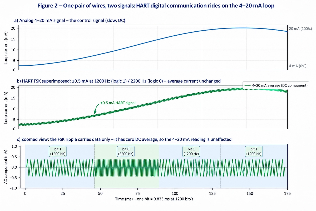
Figure 2. HART uses an FSK digital signal superimposed on the 4–20 mA loop without changing its DC average value.
4–20 mA vs. HART: What Does Each Signal Do?
| Function | 4–20 mA Analog Channel | HART Digital Channel |
|---|---|---|
| Main purpose | Real-time valve position setpoint | Configuration, monitoring and diagnostics |
| Direction | Control system → positioner | Bidirectional communication |
| Communication | Continuous analog current | Digital FSK communication |
| If unavailable | Normal valve control is lost | Normal 4–20 mA control can continue |
| Typical information | Requested valve position | Parameters, actual position, status, alarms and diagnostics |
| Separate communication cable | Not applicable | Normally not required |
The key point is that HART complements 4–20 mA rather than replacing it in a typical valve positioner application.
What Can HART Do in a Valve Positioner?
The exact capabilities depend on the positioner model, firmware, and host system, but HART-enabled POWERFLOW positioners can provide access to functions such as:
Remote Parameter Configuration
Engineers can configure supported parameters such as valve characteristics, action direction, travel limits, dead band, tight shut-off functions, control parameters, and other device settings.
Automatic Calibration and Initialization
Supported positioners can automatically identify parameters such as zero point, travel range, action direction, and actuator dynamic characteristics.
For projects involving many control valves, consistent commissioning across multiple devices can be just as valuable as the reduction in manual setup time.
Valve Position and Status Monitoring
HART can be used to digitally read device and valve information such as actual position, setpoint deviation, alarm status, travel statistics, and operating data, depending on the model and firmware.
Diagnostics
Available diagnostic information can help maintenance teams identify changes in valve or actuator behavior and investigate potential problems before they develop into larger process issues.
HART therefore adds something that a basic analog loop cannot provide on its own:
Access to the condition and configuration of the field device.
When Is a HART Valve Positioner Worth Using?
HART is useful, but that does not mean every control valve application requires it.
Applications Where HART Adds Significant Value
Large Plants with Many Distributed Valves
In facilities with hundreds of control valves, manually visiting every valve to check parameters or perform routine configuration can be inefficient.
HART allows compatible systems to access device information remotely and can support more standardized parameter management and maintenance records.
Critical Valves Requiring Traceability
For critical control loops or valves requiring periodic testing and documented maintenance, digital access to configuration and device information can improve traceability.
Difficult-to-Access Installation Locations
Valves may be installed on elevated pipe racks, in hazardous areas, cleanrooms, high-temperature areas, or locations with restricted access.
Remote communication can reduce the number of routine visits required to these locations.
Applications Requiring Periodic Condition Checks
Processes involving crystallization, coking, changing packing friction, or other conditions that can affect valve movement may benefit from periodic review of position deviation, movement statistics, alarms, and other available diagnostic information.
Plants with Existing HART Infrastructure
If the DCS already uses HART-compatible I/O cards, multiplexers, or an asset management system, adding HART-enabled field devices can be relatively straightforward.
When May HART Not Be Necessary?
HART is not automatically the best choice for every application.
A basic or non-HART smart positioner may be sufficient when:
- Only a small number of valves are installed and they are easy to access.
- The application requires relatively simple valve control.
- The plant has no HART host, HART-compatible I/O, or asset management system to use the additional data.
- Existing independent position feedback and established manual maintenance procedures already meet the operational requirements.
The practical value of HART comes from turning valve and positioner status into accessible digital information. If no system or maintenance process will use that information, simply specifying HART may provide limited additional benefit.
How Is a HART Valve Positioner Connected?
One major advantage of HART is that normal point-to-point communication uses the existing 4–20 mA loop.
A separate communication cable is generally not required.
However, the loop must meet the electrical requirements for reliable HART communication.
Why Does Loop Resistance Matter?
One of the most common causes of HART communication problems is insufficient loop impedance.
For reliable HART communication, the total loop resistance is generally required to be approximately 230–250 Ω or higher.
For the applicable POWERFLOW HART models discussed here, the positioner input impedance is approximately 120 Ω. If the DCS output card drives the positioner directly and there is insufficient additional loop resistance, a HART communicator may fail to detect the device or communication may be intermittent.
A common solution is to add an appropriate 250 Ω resistor to the loop or confirm that the I/O card already provides the necessary resistance.
At the same time, the available loop voltage must be checked to ensure sufficient voltage remains for the positioner after accounting for the additional voltage drop.
Engineering Tip: If the positioner responds correctly to the 4–20 mA signal but the HART communicator cannot detect it, check the loop resistance before assuming that the positioner or communicator is faulty.
What About Intrinsically Safe Installations?
For intrinsically safe (Ex ia) installations, the safety barrier must also be compatible with HART communication.
A barrier or isolation device with unsuitable filtering characteristics may attenuate the HART FSK signal and prevent reliable communication.
Therefore, HART compatibility should be checked when selecting barriers and other loop components.
How Can Engineers Access HART Data?
Depending on the plant architecture, a HART valve positioner can be accessed using several types of tools.
| Tool or System | Typical Use |
|---|---|
| Handheld HART communicator | On-site commissioning, configuration and troubleshooting |
| HART-enabled DCS I/O | Integration of device information into the control system |
| HART multiplexer + asset management system | Centralized monitoring and management of multiple field devices |
| Laptop + HART modem + DD/DTM | Device configuration and advanced maintenance functions |
The exact information and functions available depend on the positioner, device description, software environment, and host system.
Typical Applications of HART Valve Positioners
HART valve positioners are particularly useful in industries where control valves are numerous, critical, widely distributed, or difficult to access.
Oil & Gas
Large oil and gas facilities often have many control valves installed across hazardous areas and widely distributed process units.
HART communication can reduce routine field visits and provide easier access to device configuration and status information.
For example, POWERFLOW IP6000d flameproof smart valve positioners are designed for pneumatic control valves used in hazardous industrial environments where Ex d protection and HART communication are required.
Chemical and Petrochemical
Processes involving crystallization, coking, corrosion, or changing packing friction can affect valve performance over time.
Available HART diagnostics and operating data can help maintenance teams identify changes and plan inspection or maintenance.
Power Generation
Control valves in feedwater, desuperheating, bypass, and other high-temperature or high-pressure applications may be installed in demanding environments.
Remote access to positioner status can reduce unnecessary time spent near difficult or hazardous equipment.
POWERFLOW has also applied IP6000 remote-mounted smart valve positioners in a power plant where strong pipeline vibration was a key operating challenge.
Pharmaceutical and Other Process Industries
Where equipment status, parameter management, or maintenance records are important, HART can provide additional digital access to field-device information.
How to Select a HART Valve Positioner
HART communication is only one part of positioner selection. The positioner must also match the valve, actuator, control system, and operating environment.
Before selecting a model, confirm:
- Communication: Is HART required by the control system or project specification?
- Input signal: Does the 4–20 mA loop provide the required electrical conditions?
- Actuator: Single-acting or double-acting?
- Valve motion: Linear or rotary?
- Hazardous area: Is Ex ia, Ex d, or another protection concept required?
- Position feedback: Is a separate 4–20 mA position feedback signal required?
- Environment: What are the temperature, water, dust, vibration, and corrosion conditions?
- Pneumatic supply: Does the available supply pressure and air quality meet the positioner requirements?
- Functional safety: Is a SIL-certified configuration required?
- Mounting: Does the positioner need NAMUR, VDI/VDE 3845, or application-specific mounting hardware?
For a broader selection process, see our guide on how to choose the right valve positioner.
Exact specifications should always be checked against the latest product datasheet and model configuration.
POWERFLOW HART Valve Positioners
POWERFLOW offers HART communication on selected smart valve positioner models for different valve automation and hazardous-area requirements.
IP6000 Intrinsically Safe Smart Valve Positioner
The POWERFLOW IP6000 is an intrinsically safe (Ex ia) smart valve positioner designed for pneumatic control valves in hazardous industrial environments.
It supports 4–20 mA control and HART communication for remote configuration, diagnostics, and maintenance management.
IP6000d Flameproof Smart Valve Positioner
The POWERFLOW IP6000d is designed for applications requiring a flameproof Ex d smart valve positioner.
It combines 4–20 mA valve control with HART communication and is available for demanding hazardous-area applications.
IP7000 Non-Contact Smart Valve Positioner
The POWERFLOW IP7000 uses non-contact magnetic Hall position sensing, reducing mechanical contact and feedback wear.
It supports 4–20 mA HART communication and is designed for applications where long-term feedback stability and resistance to mechanical wear are important.
For a broader overview of HART-based valve automation, see the POWERFLOW HART Communication Valve Positioning Solution.
Frequently Asked Questions About HART Valve Positioners
What Is the Difference Between HART and 4–20 mA?
The 4–20 mA signal is normally used to transmit the valve position setpoint. HART is a digital communication protocol superimposed on the same current loop and is used for configuration, status monitoring, calibration, and diagnostics.
For more information about the protocol itself, refer to the official HART technology overview from FieldComm Group.
Can a Valve Positioner Work Without HART?
Yes. A HART-capable positioner can continue normal 4–20 mA valve control even when HART communication is not being used.
What is lost is access to the additional digital communication functions.
Does HART Require Additional Wiring?
Normally, no.
In a point-to-point installation, HART communication uses the same pair of wires as the 4–20 mA signal. However, the loop must provide suitable impedance, and additional resistance may be required.
Why Can't My HART Communicator Detect the Valve Positioner?
A common cause is insufficient loop resistance.
Check whether the total loop impedance meets the HART communication requirement and whether the DCS I/O card already includes the necessary resistance.
For intrinsically safe installations, also confirm that the safety barrier or isolator is HART compatible.
Can HART Be Used for Remote Calibration and Diagnostics?
Yes.
Supported functions can include automatic calibration, parameter adjustment, position and status reading, and alarm or diagnostic access.
However, HART does not eliminate the need for physical maintenance. Mechanical mounting adjustments, pneumatic leakage checks, linkage problems, and other physical issues still require on-site inspection.
Conclusion
A HART valve positioner combines conventional 4–20 mA valve control with bidirectional digital communication over the same wiring.
In typical point-to-point applications, the 4–20 mA signal remains responsible for the real-time valve position setpoint, while HART provides access to configuration, status information, calibration, and diagnostics.
HART is especially valuable when plants have many distributed valves, difficult-to-access installations, critical maintenance requirements, or an existing HART asset-management infrastructure. For simpler applications, however, a non-HART smart positioner may already provide everything the process requires.
The right choice should therefore be based not simply on whether HART is available, but on how the plant intends to use the additional device data.
Need help selecting a HART valve positioner for your application? Contact POWERFLOW for model selection and technical support.