Selecting a valve positioner is not simply a matter of choosing a 4–20 mA or “smart” model. The positioner must match the valve motion, actuator action, travel, pneumatic capacity, mounting interface, control system, environmental conditions, hazardous-area requirements, and required fail behavior.
A mismatch in any one of these areas can result in a positioner that cannot be mounted, cannot drive the actuator fast enough, cannot communicate with the control system, or does not meet the project certificate requirements.
This guide explains the information that should be confirmed before requesting a quotation or selecting a POWERFLOW intelligent valve positioner.
1. Start with the Valve and Actuator
The mechanical and pneumatic arrangement should be confirmed before communication features or diagnostics are considered.
Linear or Rotary Motion
Linear valves include globe, single-seat, angle-seat, and diaphragm valves. Rotary valves include ball, butterfly, V-ball, and eccentric rotary valves.
Although one positioner platform may support both types, the mounting hardware and feedback geometry are different. A linear application normally uses a feedback lever and linear-actuator bracket. A rotary application requires a rotary mounting kit and shaft coupling.
The IEC 60534-6-1 mounting standard defines mounting details for attaching positioners to linear control-valve actuators. Standardized interfaces improve compatibility, but they do not eliminate the need to confirm the actuator model, bracket dimensions, coupling, and available space.
| Item | Linear Valve | Rotary Valve |
|---|---|---|
| Typical valves | Globe, single-seat, angle-seat, diaphragm | Ball, butterfly, V-ball, eccentric rotary |
| Typical actuators | Diaphragm or piston | Rack-and-pinion, scotch-yoke, vane |
| Travel measurement | Millimetres | Degrees |
| Mounting | Linear bracket and feedback lever | Rotary bracket and shaft coupling |
Single-Acting or Double-Acting Actuator
A single-acting actuator normally has one pneumatic chamber and a return spring. The positioner requires one pneumatic output. A double-acting actuator has two pneumatic chambers and requires a positioner that can control both outputs.
This is a hardware selection, not merely a software setting. A single-acting positioner cannot correctly operate a double-acting actuator if it does not have the second pneumatic output.
Before selection, confirm:
- Actuator type and model
- Single-acting or double-acting construction
- Spring-to-open or spring-to-close arrangement, if applicable
- Effective actuator volume or cylinder diameter
- Required supply pressure
- Valve differential pressure and required seating force
2. Confirm the Required Travel or Rotation Angle
The actual valve travel must fall within the positioner’s supported feedback range. Do not use valve size as a substitute for travel.
For linear valves, provide the full stroke in millimetres. For rotary valves, provide the required rotation angle. Also confirm the feedback lever length and mounting geometry. With a conventional lever arrangement, the lever should generally be perpendicular to the valve stem around mid-travel.
If the travel is too short for the standard feedback range, resolution may be reduced. A short-stroke, split-mounted, or remote-sensor configuration may be more suitable. If the travel exceeds the permitted range, software calibration cannot compensate for insufficient mechanical movement.
For applications exposed to severe vibration or where mechanical feedback wear has caused repeated drift, consider a non-contact smart valve positioner or review POWERFLOW’s high-vibration valve positioning solutions.
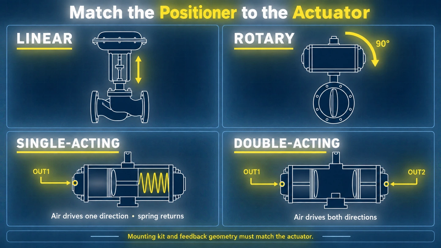 Match the valve positioner to the valve motion and actuator action.
3. Match the Control Signal and Communication Protocol
The control architecture should be confirmed before choosing the model.
4–20 mA Control
For many control loops, a two-wire 4–20 mA signal is sufficient. Confirm the minimum operating current, loop resistance, controller compliance voltage, cable resistance, and any intrinsic-safety barrier in the loop.
For split-range control, verify that the positioner remains powered and controllable at the low end of the assigned current range.
HART Communication
In a typical point-to-point HART installation, the valve setpoint is still carried by the 4–20 mA analog signal. HART adds digital communication for configuration, diagnostics, status monitoring, and asset management.
The FieldComm Group describes HART as digital signaling embedded on a 4–20 mA current loop.
Before specifying HART, check whether the plant has:
- HART-enabled I/O cards or pass-through capability
- A HART multiplexer, handheld communicator, or modem
- Compatible device-description files
- An asset-management system that will use the diagnostic data
If this infrastructure is not available, the positioner may still operate through 4–20 mA, but much of the HART functionality will remain unused.
See the POWERFLOW HART valve positioning solution for compatible product options.
PROFIBUS PA
PROFIBUS PA carries power and digital communication on the fieldbus. It is not interchangeable with a conventional analog input card. A PA installation requires a compatible segment, addressing, device integration files, and the appropriate coupler or linking device.
PROFIBUS & PROFINET International explains the PA profile and its role in process automation.
For a native PA installation, the POWERFLOW IP6500 PROFIBUS PA positioner is designed for direct digital integration.
Position Feedback
An independent 4–20 mA feedback output can return the actual valve position to the DCS, but it normally needs a separate cable pair and an available analog input channel.
If the control system already retrieves valve position digitally through HART or PROFIBUS PA, an additional analog feedback module may not be necessary.
4. Check Pneumatic Capacity and Required Stroke Time
A positioner can be correctly calibrated and still move the valve too slowly. Stroke time depends on actuator volume, supply pressure, positioner flow capacity, exhaust capacity, tubing, filter-regulator capacity, process load, and accessories.
A preliminary estimate of free-air demand is:
Free air per stroke [NL] ≈ actuator volume [L] ×
(supply gauge pressure [bar] + 1)

Required flow [NL/min] ≈ free air per stroke [NL] ÷
stroke time [min]
This is an initial estimate only. Compare the result with the positioner’s published supply and exhaust performance at the same or a similar supply pressure.
Data published at 6 bar should not be treated as the available flow at a much lower site pressure.
When a Volume Booster May Be Required
A volume booster may be appropriate when:
- The calculated flow demand exceeds the positioner’s capacity
- The actuator has a large pneumatic volume
- The pneumatic tubing is long or restrictive
- A contractual full-stroke time applies
- The valve performs an emergency shutdown function requiring rapid movement
The booster and positioner should receive adequately sized, filtered air from the same regulated supply. The booster bypass must be tuned to prevent hunting.
Oversizing the pneumatic system can make a small actuator unstable, so a booster should not be added “just in case.”
5. Verify Instrument-Air Quality
Contaminated or wet air can block pneumatic restrictions, damage seals, and reduce positioning stability. The project air specification should be checked against the requirements of the exact positioner model.
ISO 8573-1 defines compressed-air purity classes for particles, water, and oil.
A typical positioner requirement may call for Class 3 or better, but the product datasheet and installation manual remain authoritative.
Also verify that the filter regulator has enough flow capacity for the positioner, actuator, and any booster. A regulator that is too small can create an apparent positioner problem during rapid travel.
6. Confirm the Mounting and Feedback Method
Common arrangements include the following.
Mechanical Linkage
A lever or coupling mechanically transfers valve motion to the position sensor. This is widely used and economical, but correct alignment and lever length are essential.
Wear, backlash, and vibration can eventually create deadband or calibration drift.
Standardized NAMUR Mounting
Standardized interfaces simplify mounting and spare-parts management, but “NAMUR mounting” does not mean that every bracket fits every actuator.
Always request the actuator manufacturer, model, mounting dimensions, and photographs for retrofit work.
Non-Contact Feedback
Magnetic or Hall-effect sensing measures movement without direct mechanical contact in the feedback mechanism. It can reduce linkage wear and improve stability in vibration-prone applications.
It does not, however, remove the enclosure’s temperature, vibration, alignment, or installation limits.
Remote or Split Mounting
Remote sensing keeps the feedback element at the valve while relocating the electronics. This can help when the valve is exposed to excessive heat, vibration, steam cleaning, radiation, or limited installation space.
Confirm the permitted cable length and the environmental rating of both the sensor and electronics.
7. Evaluate Hazardous-Area and Environmental Requirements
Do not request only an “explosion-proof positioner.” The complete protection concept and certification marking must match the installation.
Confirm:
- Gas or dust zone
- Gas or dust group
- Temperature class
- Ambient-temperature range
- Required protection concept, such as Ex ia or Ex db
- Required certification system, such as ATEX, IECEx, EAC Ex, or China Ex
- Exact model and option code covered by the certificate
The ATEX Directive 2014/34/EU applies to equipment and protective systems intended for use in potentially explosive atmospheres in the European market.
The IECEx system provides an international framework and online certificate database for equipment used in explosive atmospheres.
Intrinsic Safety and Flameproof Protection
An Ex ia installation limits electrical energy and normally requires a correctly selected barrier or isolator together with a verified intrinsic-safety loop.
An Ex db enclosure contains an internal explosion and prevents flame transmission through its certified construction.
These protection concepts have different installation rules. Cable glands, plugs, grounding, wiring, barriers, and maintenance procedures must follow the certificate and project specification.
Always check the certificate for the exact positioner variant rather than assuming that approval for one model applies to an entire product family.
For available project documentation, review POWERFLOW certifications and technical resources.
Temperature, Ingress Protection, Vibration, and Corrosion
Check the full ambient-temperature range, including startup and shutdown conditions. The temperature class of hazardous-area equipment may restrict the maximum permitted ambient temperature.
For cold locations, also confirm whether the display remains readable even if the control function continues operating.
POWERFLOW has product certifications covering IP67 and IP69 protection on applicable models. The rating is valid only when the cable glands, plugs, conduit seals, covers, and mounting arrangement are installed correctly.
IP69 water-jet protection should not be treated as hygienic or pharmaceutical certification by itself.
For corrosive, marine, washdown, food, beverage, or pharmaceutical applications, also assess:
- Enclosure material
- Exposed fasteners
- Coating compatibility
- Cleaning chemicals
- Drainage
- Installation location
See POWERFLOW’s pharmaceutical valve positioning solutions for additional application information.
8. Define the Fail Action Correctly
Fail action must be evaluated for three separate events:
- Loss of control signal
- Loss of electrical power
- Loss of instrument air
A spring-return actuator has an inherent mechanical fail direction determined by the spring arrangement and valve trim.
A double-acting actuator has no spring-generated inherent fail position.
If instrument air remains available and the positioner or associated pneumatic circuit supports the required logic, a positioner can drive a double-acting actuator to a configured fail-open, fail-closed, or hold position after loss of signal or power.
If the air supply is also lost, additional stored energy or pneumatic hardware—such as a spring-return actuator, air reservoir, lock-up valve, or dedicated interlock—is required to achieve a defined action.
“Fail in place” is not permanent. Trapped air pressure decays through normal leakage, and process forces may move the valve.
If a minimum holding time or number of emergency strokes is required, the reservoir and pneumatic circuit must be calculated and tested.
Do not treat fail-in-place as a safety function unless the complete arrangement is assessed and implemented as part of the safety instrumented function.
IEC 61508 provides the general framework for electrical, electronic, and programmable electronic safety-related systems.
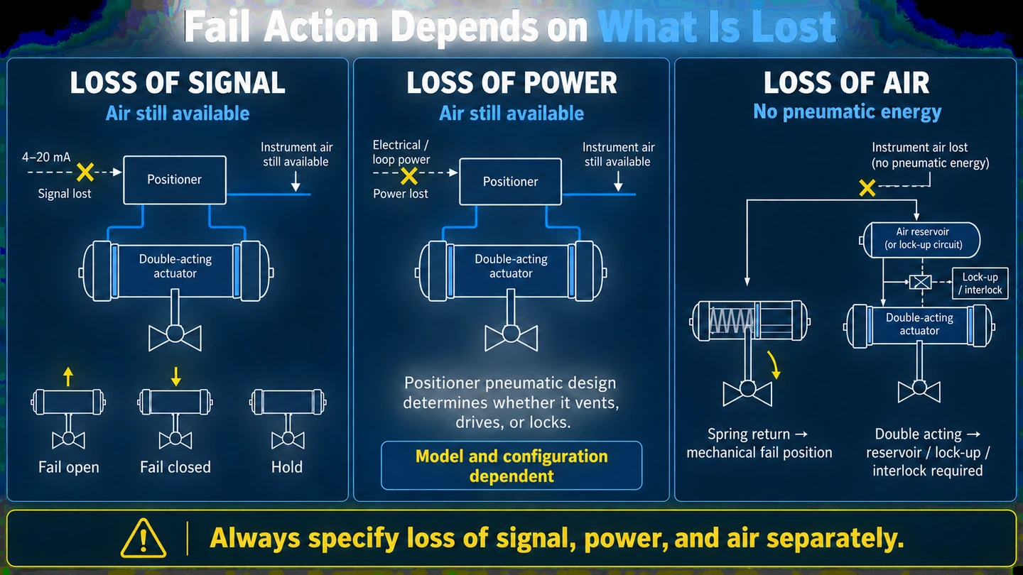 Valve positioner fail action during loss of signal, power or air supply.
9. POWERFLOW Model Selection Overview
The following table is a starting point. Final selection must be based on the exact datasheet, certificate, options, actuator data, and site conditions.
| Model | Main Difference | Typical Selection Reason |
|---|---|---|
| IP7000 | Non-contact magnetic feedback; linear and rotary applications | High vibration, reduced feedback wear, demanding outdoor or washdown installations |
| IP6000 | 4–20 mA platform with optional HART and intrinsically safe configurations | General process control and hazardous-area projects requiring Ex ia |
| IP6000d | Flameproof Ex db platform with optional HART | Projects that specifically require flameproof construction |
| IP6500 | Native PROFIBUS PA communication | Plants with an existing or planned PROFIBUS PA segment |
| IP5500 | Separate 24 V DC supply with 4–20 mA setpoint | General non-hazardous applications where four-wire architecture is acceptable |
| 1600 / 1601 | Stainless-steel compact platform for integrated valve mounting | Angle-seat and diaphragm valves, OEM skids, food, beverage, and pharmaceutical service |
| 1880S | Compact side-display construction | Restricted installation space and small integrated process valves |
| 1500 | Economical compact platform | Standardized OEM applications and cost-sensitive general service |
Browse the full POWERFLOW valve positioner range and confirm current specifications for the selected configuration.
10. Valve Positioner Selection Checklist
Provide the following information with your request for quotation.
Required to Select the Model
- Valve type and linear or rotary motion
- Actual stroke in millimetres or rotation angle in degrees
- Actuator manufacturer and model
- Diaphragm, piston, rack-and-pinion, or scotch-yoke actuator
- Single-acting or double-acting operation
- Site instrument-air pressure
- Control signal and communication protocol
- Hazardous-area classification and required certificate
- Required fail action for loss of signal, power, and air
Required to Avoid Installation Problems
- Mounting standard and actuator interface dimensions
- Full-stroke time requirement
- Actuator volume or cylinder dimensions
- Ambient-temperature range
- Ingress-protection, corrosion, vibration, and washdown requirements
- Required accessories, such as position feedback, switches, gauges, booster, lock-up valve, or remote sensor
- Photographs of the complete valve and actuator mounting area for retrofit projects
Common Selection Mistakes
Assuming Actuator Action from the Valve Type
A butterfly valve may use either a spring-return or double-acting actuator. The valve type alone does not identify the required pneumatic outputs.
Specifying Only “Ex ia IIC T6”
The complete selection also depends on zone, ambient-temperature range, certificate system, and the exact certified model code.
Ignoring Pneumatic Flow
A positioner may control accurately at steady state but fail the required stroke time because its supply or exhaust capacity is too low—or because the filter regulator and tubing are restrictive.
Providing Only the Valve Model
The valve body model does not identify the actuator, travel, mounting interface, or bracket.
Retrofit projects should include the actuator nameplate and clear mounting photographs.
Confusing HART with PROFIBUS PA
HART normally adds digital data to a 4–20 mA loop. PROFIBUS PA is a digital fieldbus architecture.
They are not interchangeable, so the DCS or PLC interface should be confirmed first.
Frequently Asked Questions
Does every pneumatic control valve need a positioner?
No. A simple on/off valve may only require a solenoid valve.
A positioner is normally used when the valve must modulate accurately, overcome changing process forces, respond dynamically, provide characterization, or supply diagnostic information.
Can one positioner be used for both linear and rotary valves?
The electronics platform may support both, but the feedback components, mounting bracket, coupling, and initialization must match the actual motion and actuator.
Can a positioner make a double-acting valve fail closed?
It can drive the actuator to a selected position after loss of signal or power if instrument air remains available and the pneumatic design supports that action.
If instrument air is also lost, a spring, reservoir, lock-up circuit, or another engineered fail-safe arrangement is required.
When is a volume booster needed?
A booster may be needed when the required actuator flow exceeds the positioner’s capacity, the actuator volume is large, tubing is restrictive, or a specified stroke time must be met.
Confirm the requirement through pneumatic sizing and dynamic testing.
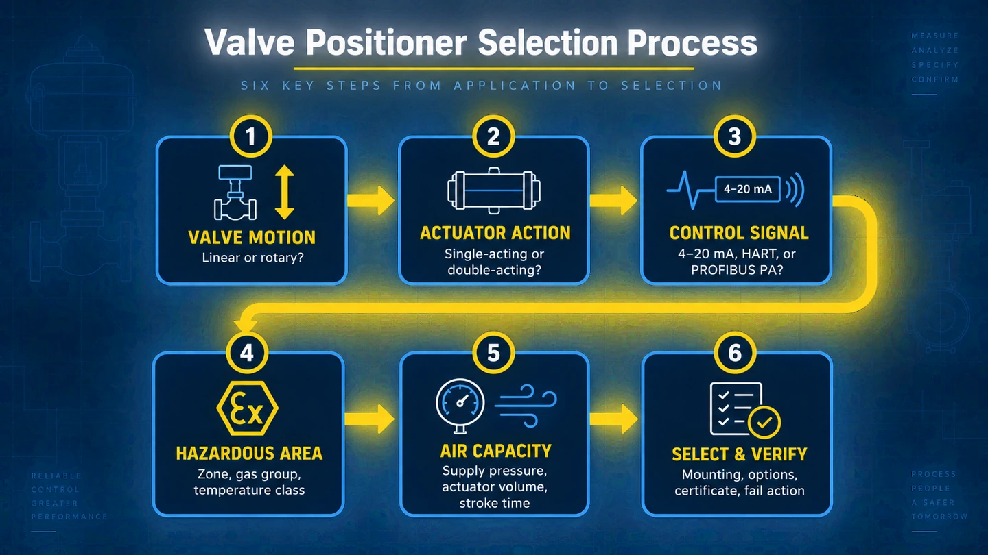 A practical six-step process for selecting a pneumatic valve positioner.
Need Help Selecting a Valve Positioner?
Send POWERFLOW your valve type, actuator model, travel, action, supply pressure, control signal, required stroke time, hazardous-area classification, ambient conditions, and fail-action requirement.
Our engineering team can review the application and recommend a suitable configuration.
Explore Smart Valve Positioners · Contact the POWERFLOW Engineering Team
Product specifications, communication functions, environmental ratings, and certification coverage vary by model and configuration. Confirm the latest datasheet, installation manual, certificate, and ordering code before final selection.