I often see buyers start with a model name. That creates risk. A wrong positioner can cause delay, rework, and unsafe site use.1
I choose the right positioner by matching it to the valve, actuator, signal, site environment, certification need, and project risk. I do not start with the most advanced model. I start with the real control task and the real installation condition.
When I discuss selection with valve makers, integrators, and procurement teams, I usually slow the process down at the start. I ask basic questions first. I ask about the valve type, actuator type, action mode, control signal, feedback need, hazardous area, temperature, vibration, and mounting space.
This may sound simple. It is not always simple in real purchasing work. Many positioner problems do not start in production. They start during selection. A buyer may compare price before confirming single acting or double acting. An engineer may ask for HART before confirming whether the control system will use it. A distributor may ask for explosion-proof housing before checking the exact certification request from the project.
I work from the manufacturer side. I see inquiries, pre-sales selection notes, assembly work, calibration, testing, and final inspection. That view has taught me one clear lesson. The best positioner is not always the one with more options. The best positioner is the one that fits the valve package and reduces mismatch risk.
What must I confirm before I ask for a model or price?
I see many selection mistakes begin with a quick price request. That feels efficient, but it can hide the wrong actuator, wrong air logic, and wrong mounting plan.
I first confirm the valve type, actuator type, and single-acting or double-acting requirement. These points decide the positioner air output, mounting method, travel feedback, and basic compatibility before I compare models or prices.2
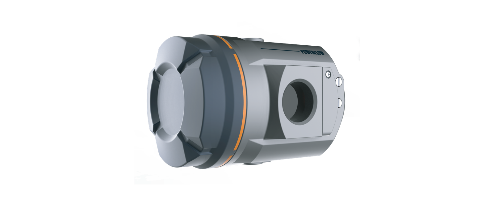
I start with the valve package, not the catalog page
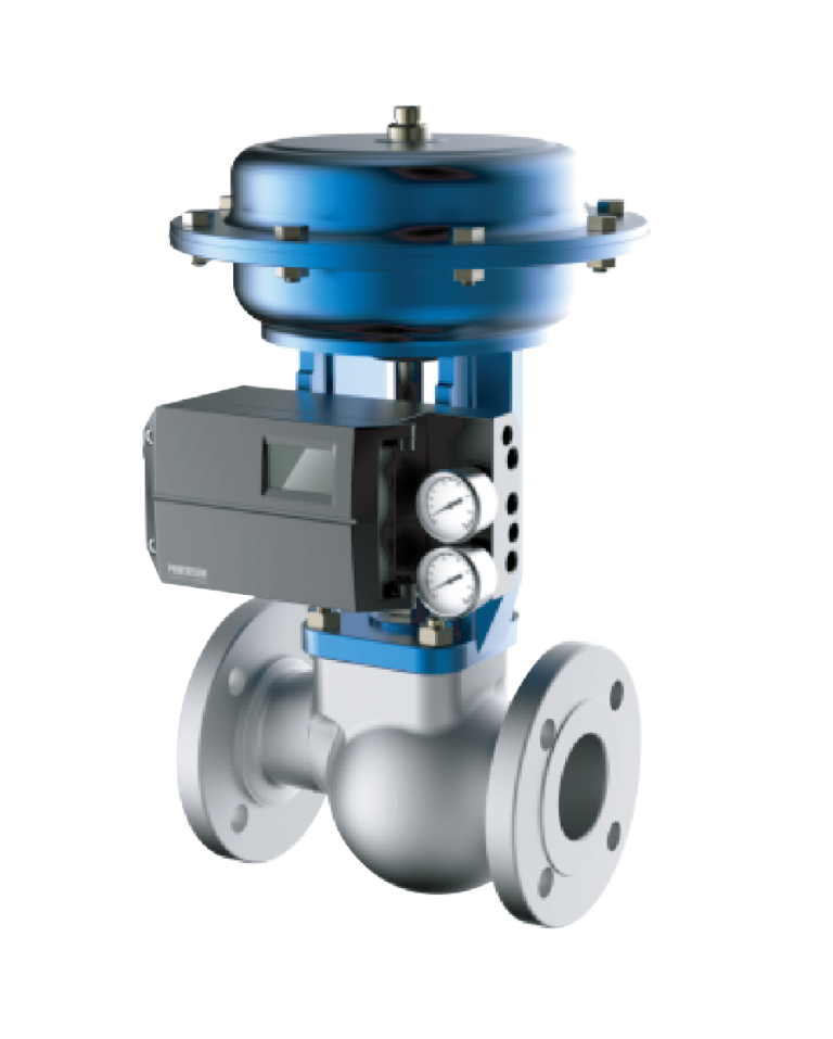
When I receive an inquiry, I try to define the valve package in plain terms. I ask whether the valve is rotary or linear. I ask whether the actuator is pneumatic diaphragm, pneumatic piston, or another design. I ask whether the actuator needs spring return or air-to-air control. I also ask about the travel range and the mounting standard if the buyer knows it.
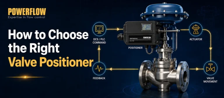
These details matter because the positioner does not work alone. It reads valve movement and sends air to the actuator.3 If the mechanical movement and air logic do not match, the best electronic function will not solve the problem. The positioner may be hard to calibrate. The valve may hunt. The project team may need new brackets or a different unit.
| What I confirm first | Why I confirm it | Selection risk if I skip it |
|---|---|---|
| Valve type | It affects travel feedback and mounting | Wrong linkage or poor feedback accuracy |
| Actuator type | It affects air output and control behavior | Slow response or unstable control |
| Single or double acting | It decides output port logic | Wrong air connection and failed commissioning |
| Travel angle or stroke | It affects calibration range | Incomplete stroke or false position reading |
| Mounting standard | It affects brackets and installation | Rework at site or delayed assembly |
I treat “standard model” as a starting point
I do not treat a standard model as a complete answer. A standard model can be right, but only after I match it to the valve package. In our factory work, a positioner may pass calibration and inspection, but it still must fit the actual actuator and site requirement. Factory quality cannot fix wrong selection. It can only confirm that the selected unit performs within its intended design.
I also ask for photos, drawings, or actuator nameplate data when the inquiry is not clear. This step may take extra time. It often saves more time later. I would rather clarify the actuator action before production than explain a mismatch after shipment.
How do I match the positioner to the control signal and communication need?
I often hear feature names first. A buyer says 4–20 mA, feedback, or HART. The real question is what the control system must do with the valve.
I select signal and communication options based on control, monitoring, and diagnostic needs. A 4–20 mA input controls valve position. Feedback confirms valve position. HART supports setup and diagnostics when the system and staff can use it.
If HART communication is required, learn how a HART valve positioner works before selecting the appropriate model.
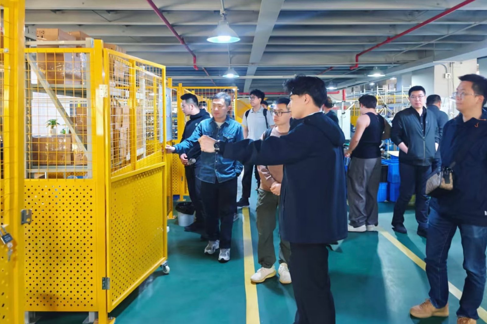
I separate control from monitoring
The 4–20 mA input is usually the main control command.4 It tells the positioner where the valve should move. A feedback signal is different. It tells the control system where the valve is or what the positioner reports as position. These two signals may look similar on paper, but they serve different tasks.
I have seen inquiries where feedback is requested because it sounds useful. I still ask whether the control system has an input channel for it. I ask whether the plant team will use it for display, alarm, interlock, or data logging. If the answer is no, the extra option may not add value. If the answer is yes, feedback can reduce uncertainty during operation and troubleshooting.
| Option | Main use | I choose it when | I avoid adding it when |
|---|---|---|---|
| 4–20 mA input | Position control | The valve needs modulating control | The valve is only on/off and does not need position control |
| Position feedback | Monitoring | The system needs actual position data | No input channel or no monitoring plan exists |
| HART | Setup and diagnostics | The site has tools, system support, and staff use | The feature will not be connected or maintained |
| Limit switches | Open/close status | The control task needs end-position signals | Continuous position data is already enough |
| Local display | Field checking | Technicians need quick on-site reading | Space, cost, or environment makes it less useful |
I do not treat HART as a decoration
HART can be very useful. It can help with setup, reading device information, and checking diagnostics if the system supports it.5 I do not recommend it only because the word looks strong in a specification. I ask how the customer plans to use it. I ask whether the DCS, handheld communicator, or maintenance team supports HART work.
This matters because unused features can still create selection and documentation work. They can affect procurement cost, approval documents, and stock control. A simple 4–20 mA positioner may be the better choice for a small project with simple control and no diagnostic workflow. A HART positioner may be the better choice for a plant that wants remote checking and better maintenance data.
The key point is not to choose fewer features. The key point is to choose used features. A function that solves a real task is valuable. A function that nobody connects, reads, or maintains is only a label.
If you are still comparing available technologies, see our introduction to smart valve positioners and their applications.
How do site conditions change my positioner choice?
I have seen projects where the catalog match looked fine, but the site condition changed the answer. Dust, water, gas risk, cold, heat, vibration, and space can override a simple model choice.
I check hazardous area requirements, protection level, temperature, vibration, EMC needs, and installation limits before I confirm a positioner. Site conditions decide whether the selected unit will be safe, legal, and reliable in real use.

I treat certification as a project requirement
A hazardous area request must be handled with care. I do not assume one certificate fits every market or every project. I ask which certification is needed. I ask whether the project needs ATEX, IECEx, or another local approval.6 I also ask about gas group, temperature class, and zone requirement7 when the customer has that information.
As a manufacturer, I can support selection by checking our available certified versions and documents. I do not replace the project authority or site safety review. The buyer or project team still needs to confirm the final requirement. This is important because certification is not only a product label. It is part of project compliance.
| Site factor | Why I check it | Possible selection impact |
|---|---|---|
| Hazardous area | It affects explosion protection need | Certified enclosure or special version may be required |
| IP protection | It affects dust and water resistance | IP66 or IP67 type protection may be needed8 |
| Temperature | It affects electronics, seals, and display | Low-temperature or high-temperature version may be needed |
| Vibration | It affects sensor stability and terminals | Stronger structure or tested configuration may be needed |
| EMC environment | It affects signal stability | EMC-compliant design and correct wiring matter9 |
| Mounting space | It affects installation and maintenance | Compact body or custom bracket may be needed |
I look beyond the brochure line
A brochure value is useful, but it is not the whole site picture. A temperature range may look suitable, but the positioner may be installed near a hot pipe, under direct sunlight, or in a cold outdoor area. An IP rating may look suitable, but cable glands and installation quality also affect real protection. A vibration test result may look strong, but poor mounting can still create movement and unstable feedback.
In our production and quality work, we check key performance items through calibration and testing. That gives confidence in the product leaving the factory. It does not remove the need for correct site selection. I want the selected positioner to match the real conditions because site problems are harder to fix after installation.
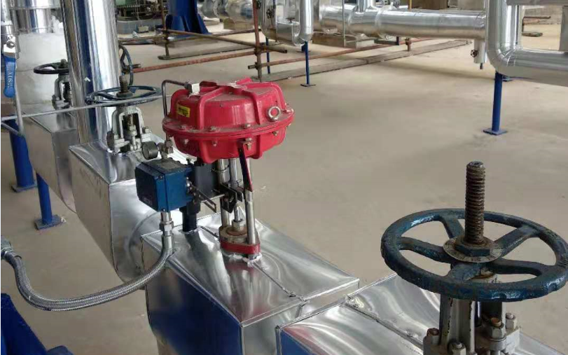
I also ask about air supply quality. A pneumatic positioner needs clean and stable air. Dirty air, water, or oil can cause sticking and poor response. This point is easy to forget because buyers focus on electronics. I always see the positioner as both an electronic device and a pneumatic control device.
Why is a higher configuration not always the safer choice?
I understand why buyers ask for the highest configuration. It feels safer. Yet I have learned that more functions can add cost, lead time, and mismatch risk when the application does not need them.
I choose the lowest configuration that safely meets the control task, site condition, and compliance need. A higher configuration is useful only when it reduces real risk or supports real operation.
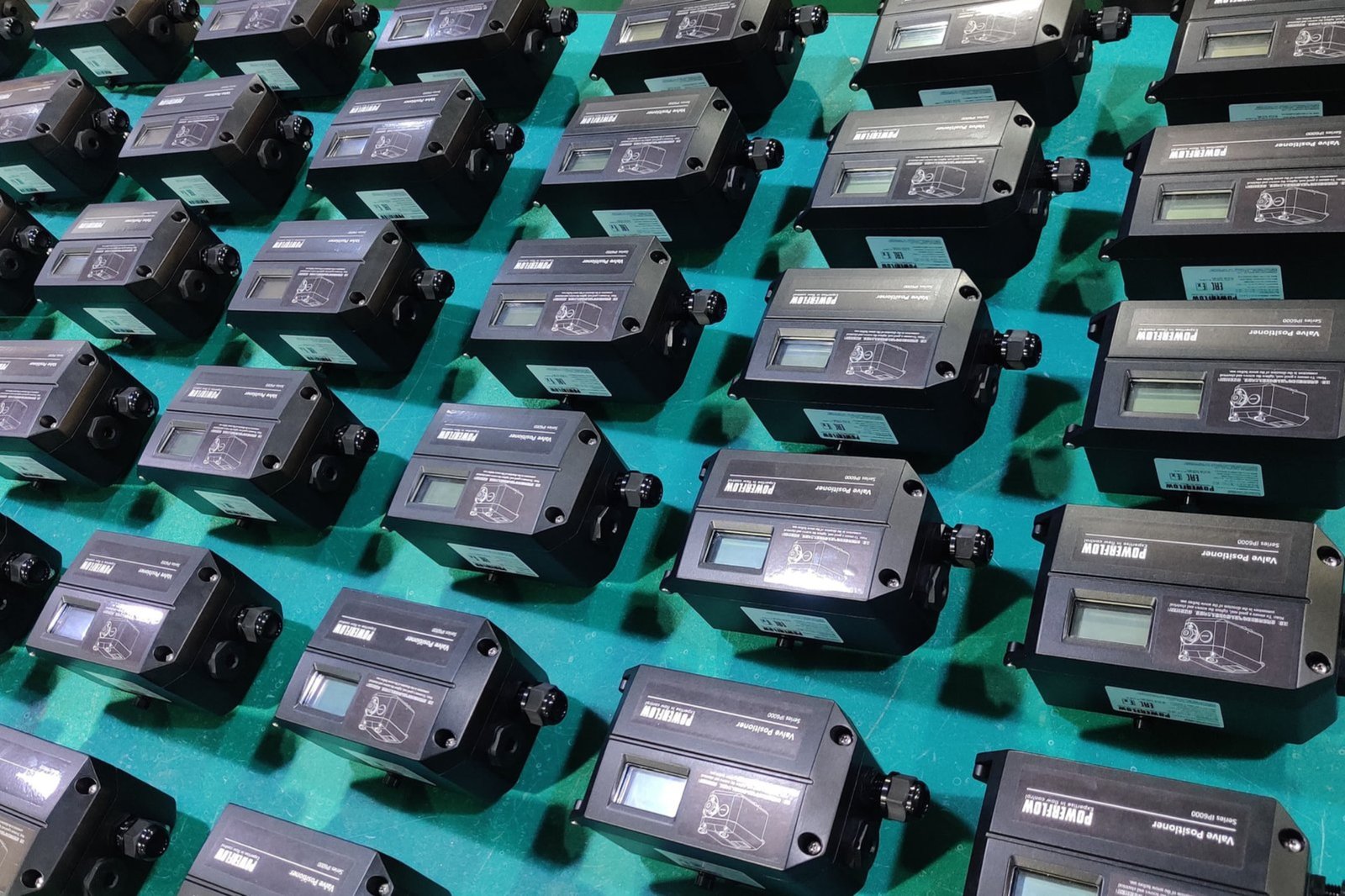
I compare risk, not only features
A feature-rich positioner may be correct for a complex plant. It may also be wrong for a simple valve package. More options can mean more wiring, more parameter setting, more documents, more approval steps, and more stock differences. If the project team does not use these options, they may not reduce risk.
I use a simple question. What problem does this option solve? If the answer is clear, I support the option. If the answer is not clear, I check again. This approach helps me avoid selling complexity as safety. It also helps buyers avoid paying for functions that do not help commissioning or operation.
| Higher option | It helps when | It may not help when |
|---|---|---|
| HART communication | Diagnostics and remote setup are used | No HART tool or system support exists |
| Explosion-proof enclosure | Hazardous area approval requires it | The site is non-hazardous and does not need it |
| Feedback output | Position monitoring is required | No control system input is available |
| Stainless steel parts | Corrosion risk is high | Indoor clean service does not need it |
| Low-temperature version | The site is very cold | Normal ambient temperature applies |
| Custom bracket | Standard mounting does not fit | Standard actuator interface is available |
I respect cost, but I do not chase the cheapest answer
The lowest price can create a hidden cost if the selection is wrong. The highest configuration can also create a hidden cost if it is unnecessary. I try to find the middle point. That point is the configuration that matches the valve and lowers project risk.
From the factory side, I see how customization affects production and delivery. A custom mounting bracket, special housing, feedback board, or communication board can be practical. It can also require more confirmation before production. I prefer to define these items early. Then the assembly, calibration, and final inspection can follow a clear requirement.
I also think about spare parts and future replacement. If a distributor supplies many different versions without a reason, stock becomes harder to manage. If a plant has too many special configurations, maintenance becomes harder. A good selection should support the first installation and the later service work.
How do I reduce commissioning and compliance risk before ordering?
I have seen problems that could have been avoided with one more round of clarification. A small missing detail can become a delayed valve package or a field change.
I reduce risk before ordering by confirming a selection sheet, drawings or photos, certifications, signal plan, air connection, mounting method, and inspection needs. Clear data before production reduces commissioning rework.
![valve positioner ordering checklist]https://powerflow-positioner.com/wp-content/uploads/2026/05/06_secure_packaging_200x128.jpg "Valve positioner ordering and commissioning checklist")
I use a practical pre-order checklist
Before I confirm an order, I like to put the main points into one clear selection record. This record does not need to be complex. It only needs to remove guesswork. I want the sales team, engineering team, production team, and customer team to read the same requirement.
For OEM or ODM work, this step is even more important. The customer may need a special label, enclosure, feedback option, firmware setting, or mounting kit. Each item should be written down. If the requirement is only discussed in a message thread, it can be missed. If it is placed in a confirmed sheet, the factory can build and inspect against it.
| Pre-order item | What I confirm | Why it reduces risk |
|---|---|---|
| Valve and actuator data | Type, stroke, action, mounting | It prevents mechanical mismatch |
| Signal plan | Input, feedback, HART, switches | It prevents wiring and system mismatch |
| Certification need | ATEX, IECEx, CE, EAC, or other need if required | It prevents approval and site acceptance issues |
| Environment | Temperature, IP level, vibration, corrosion | It prevents wrong enclosure or option choice |
| Air supply | Pressure range and air quality plan | It prevents unstable pneumatic behavior |
| Inspection request | Calibration, documents, packing, labels | It prevents shipment and acceptance disputes |
I connect factory testing with field needs
A positioner can be calibrated and tested at the factory, but the field still needs correct installation. In our manufacturing process, we pay attention to PCB assembly, firmware loading, precision calibration, stroke testing, temperature-related checks, vibration-related checks, EMC-related design control, and final inspection. These steps help confirm that the unit is built correctly.
I still ask the customer to think about the field task. The actuator must move freely. The air pipes must be correct. The signal wiring must be clean. The mounting bracket must be firm. The feedback lever or sensor arrangement must follow the intended movement. A good positioner cannot overcome a jammed valve, wet instrument air, wrong wiring, or a loose bracket.
I also recommend early document checking for projects with formal compliance needs. The purchase team should confirm whether certificates, manuals, test records, labels, and declarations meet the project requirement. This is not exciting work, but it prevents trouble. Compliance risk often appears late, and late corrections cost more time.
When I help with selection, I try to make the final choice boring in a good way. The positioner should fit. The wiring should make sense. The documents should match. The installation team should not need to guess. That is how I define a good selection.
Conclusion
I choose the right positioner by matching real valve, signal, site, and compliance needs. The best choice reduces mismatch, rework, and commissioning risk.
"[PDF] PNEUMATICALLY ACTUATED CONTROL VALVES IN OIL SYSTEMS", https://www.emerson.com/is/content/emerson/en/final-control/flow-controls/products/eccentric-plug-valves/documents/D101881X012.pdf. Engineering guidance on control-valve installation and accessories notes that actuator, positioner, mounting, and service-condition mismatches can impair commissioning and safe operation; this supports the general risk described here, though it does not quantify delay or rework rates for this article's cases. Evidence role: general_support; source type: institution. Supports: A neutral engineering source should support that control-valve accessories must be selected and installed to match the actuator and service conditions, because mismatches can affect commissioning and safe operation.. Scope note: The source would provide general engineering support, not direct evidence for the author's observed projects. ↩
"Single Acting vs. Double Acting Positioners: Pros and Cons", https://www.transmittershop.com/blog/single-acting-vs-double-acting-positioners-pros-and-cons/. Control-valve accessory guidance describes positioner compatibility as dependent on actuator type and action, travel geometry, feedback linkage, and mounting arrangement, supporting the need to confirm these factors before model selection. Evidence role: mechanism; source type: institution. Supports: The source should explain that positioners must be matched to actuator action, travel type, air-output arrangement, and mounting/feedback configuration.. ↩
"Control valve - Wikipedia", https://en.wikipedia.org/wiki/Control_valve. A valve positioner is commonly defined as a feedback device that compares commanded and actual valve position and adjusts pneumatic pressure to the actuator to reduce the error. Evidence role: definition; source type: encyclopedia. Supports: The source should define a valve positioner as a device that compares a control signal with valve position feedback and adjusts actuator air pressure.. ↩
"4-20 mA - Wikipedia", https://en.wikipedia.org/?title=4-20_mA&redirect=no. References on industrial current-loop signaling describe 4–20 mA as a standard analog instrumentation signal used to transmit process-control commands or measurements, supporting its treatment here as a common positioner input. Evidence role: definition; source type: encyclopedia. Supports: The source should support that 4–20 mA current loops are widely used for analog instrumentation and control signals in process industries.. ↩
"Highway Addressable Remote Transducer Protocol - Wikipedia", https://en.wikipedia.org/wiki/Highway_Addressable_Remote_Transducer_Protocol. HART protocol documentation describes digital communication over analog instrument wiring for device configuration, identification, status, and diagnostic data, supporting the article's claim when compatible tools or host systems are present. Evidence role: mechanism; source type: institution. Supports: The source should show that HART enables digital communication over analog instrumentation loops for configuration, device information, and diagnostics.. ↩
"ATEX directives - Wikipedia", https://en.wikipedia.org/wiki/ATEX_directives. Official hazardous-atmosphere certification guidance identifies ATEX and IECEx as equipment conformity schemes for explosive atmospheres, supporting the need to verify the approval scheme required by the project location and specification. Evidence role: expert_consensus; source type: government. Supports: The source should support that equipment for explosive atmospheres is subject to certification schemes such as ATEX in the EU and IECEx internationally, with local acceptance requirements.. Scope note: Such a source supports the certification framework generally; the final approval requirement still depends on the particular jurisdiction and project authority. ↩
"[PDF] HAZARDOUS AREA GUIDE for ATEX & IECEx (Zones/Groups) - cmlex", https://www.cmlex.com/wp-content/uploads/hazardous-area-guide.pdf. Hazardous-area classification standards use zone classification, gas grouping, and temperature class to determine whether electrical equipment is suitable for an explosive atmosphere. Evidence role: definition; source type: institution. Supports: The source should define zone classification, gas grouping, and temperature class as parameters used in hazardous-area equipment selection.. ↩
"IP code - Wikipedia", https://en.wikipedia.org/wiki/IP_code. IEC 60529 defines IP Code ratings for enclosure protection against dust and water ingress; IP66 and IP67 ratings indicate different tested levels of dust-tightness and water protection relevant to field-device selection. Evidence role: definition; source type: institution. Supports: The source should define IP66 and IP67 as ingress-protection ratings related to dust and water exposure under IEC 60529.. ↩
"[PDF] Electromagnetic Compatibility Control Plan - MIT", https://snebulos.mit.edu/projects/acis/file_cabinet/0/01205/01205_rA.pdf. EMC standards for measurement and control equipment address immunity and emissions requirements, and installation guidance commonly treats wiring and grounding as factors in maintaining reliable instrument signals. Evidence role: general_support; source type: institution. Supports: The source should support that industrial measurement and control devices are subject to EMC requirements and that installation practices can influence signal integrity.. Scope note: This would support the general engineering principle, not prove that any particular installation in the article has EMC-related problems. ↩