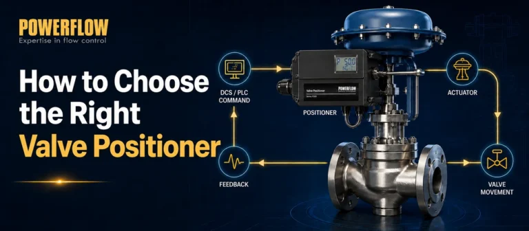
Buyers often ask me for a simple count of positioner types. That question hides real risks—mismatched valves, project delays, and unfair quotes. Let me reframe it.
There is no single fixed number of positioner types.1 The count changes depending on what you measure: control signal, actuator motion, communication needs, or explosion-proof requirements. Instead of memorizing a number, use the right selection dimensions to match your valve and project safely.
I learned this from talking with valve makers and EPC engineers. They don't need a textbook list. They need to avoid wrong matches. So I will break this down the same way I do on specification calls. Each question you see below came from a real project.
How do I group positioners by control signal and intelligence?
A customer once told me he only wanted “electro-pneumatic” positioners. But his control room sent a 4-20 mA signal. He didn’t know that smart positioners also use that signal—he missed the best fit.
Positioners fall into three main control signal groups: pneumatic (3-15 psi), analog electro-pneumatic (4-20 mA), and smart/digital with microprocessor2. But digital ones often include HART, fieldbus, or diagnostics. So the count depends on how you split those sub-features.
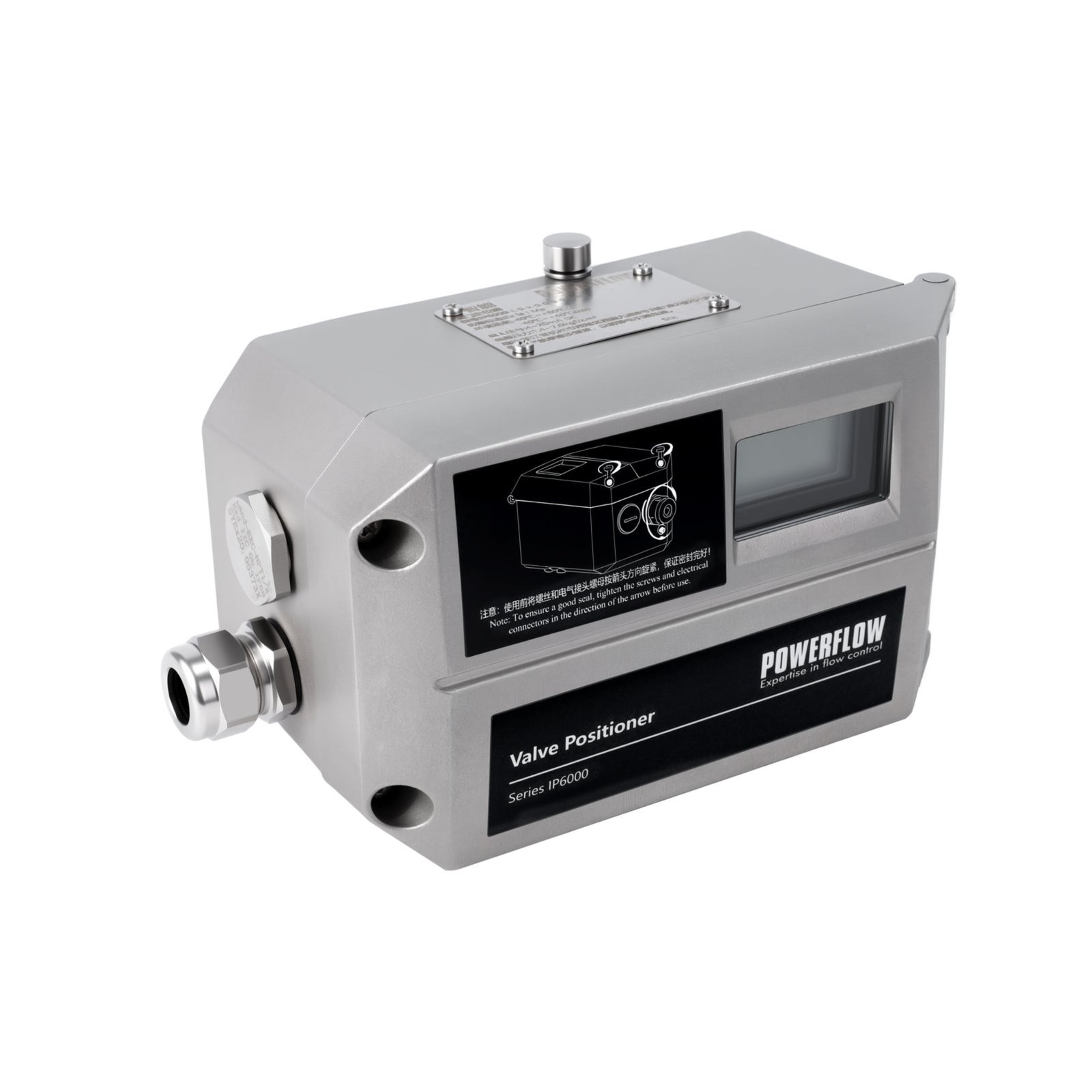
The first split happens at the signal level. Pneumatic positioners receive an air pressure signal, usually 3 to 15 psi.3 They contain no electronics. They simply convert that pressure into a valve stem position. These are common in plants that still use pneumatic control rooms. Then you have electro-pneumatic positioners. They take an electrical signal, typically 4-20 mA, and use a small flapper-nozzle or piezoelectric system to convert it into a pneumatic output. This adds flexibility but still no onboard intelligence.
Smart positioners build on that same 4-20 mA input but add a microprocessor.4 They self-calibrate, run diagnostics, and can talk back to the control system.5 The tricky part is that many engineers treat “smart” as a separate type alongside analog. But a smart positioner is still electro-pneumatic. It just adds intelligence. Then we get into communication. HART overlays digital data on the same 4-20 mA wires.6 Others use Foundation Fieldbus or Profibus and are completely digital.7 If you count HART as a separate type from analog 4-20 mA, you add more numbers. But from a signal standpoint, both still use that same current loop. I have seen projects where three suppliers quoted under “electro-pneumatic type” but one gave analog without HART, one gave smart with HART, and one gave a fieldbus unit. The prices were worlds apart, and the buyer couldn’t compare them fairly. So the real question is: what signal does your system send and what level of data do you need back? That gives you the right count for your project.
How do I match positioner types to my actuator and valve motion?
Another time, a buyer asked for “linear positioners.” That sounds specific, but he had rotary valves. That mismatch would have ruined the project.
Positioners must match actuator type: linear for globe or diaphragm actuators, rotary for rack-and-pinion or scotch-yoke.8 Then further split by single-acting (spring return) or double-acting. A linear double-acting positioner is not the same type as a rotary single-acting one.
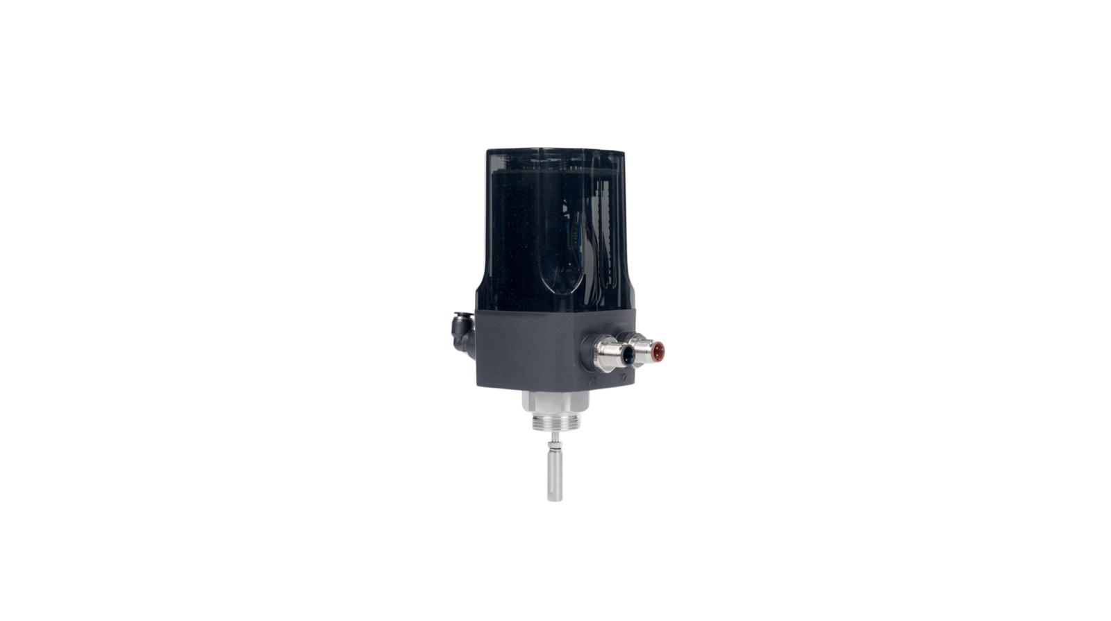
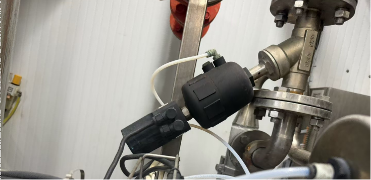
Actuator matching is a classification layer that stands on its own. It does not care about signal type. A pneumatic positioner can be linear, and a smart digital one can be linear too. What changes is the mounting bracket, the feedback arm, and the internal linkage design. Linear positioners connect to a stem moving up and down. Rotary positioners have a shaft that turns, usually through a Namur or similar coupling. Many modern smart positioners can handle both motions through software configuration, but the hardware still needs the right kit. If you order a positioner described only as “smart, double-acting,” you still need to specify whether the actuator moves linearly or rotates.
I recall an inquiry from a system integrator. The specification read: “Intelligent positioner, 4-20 mA, double-acting.” Nothing about motion. When I called to ask, they said it was for a ball valve with a rotary rack-and-pinion actuator. That single clarification changed the product code entirely. If I had shipped one for a linear diaphragm actuator, nothing would have fit. The mounting bracket would be wrong, and the feedback linkage would be misaligned. So in project discussions, I don’t count positioner types without first asking: is your actuator linear or rotary, and does it need single or double acting? Those three answers multiply the number of possible configurations. A single-acting rotary smart positioner is one type. A double-acting linear analog one is another. Listing them all as one flat number makes no sense.
What about explosion-proof, communication, and site conditions?
You might assume that a positioner type is finished once you choose smart. But one call from a chemical plant changed my mind. They needed ATEX, IP66, and SIL3—all in one.
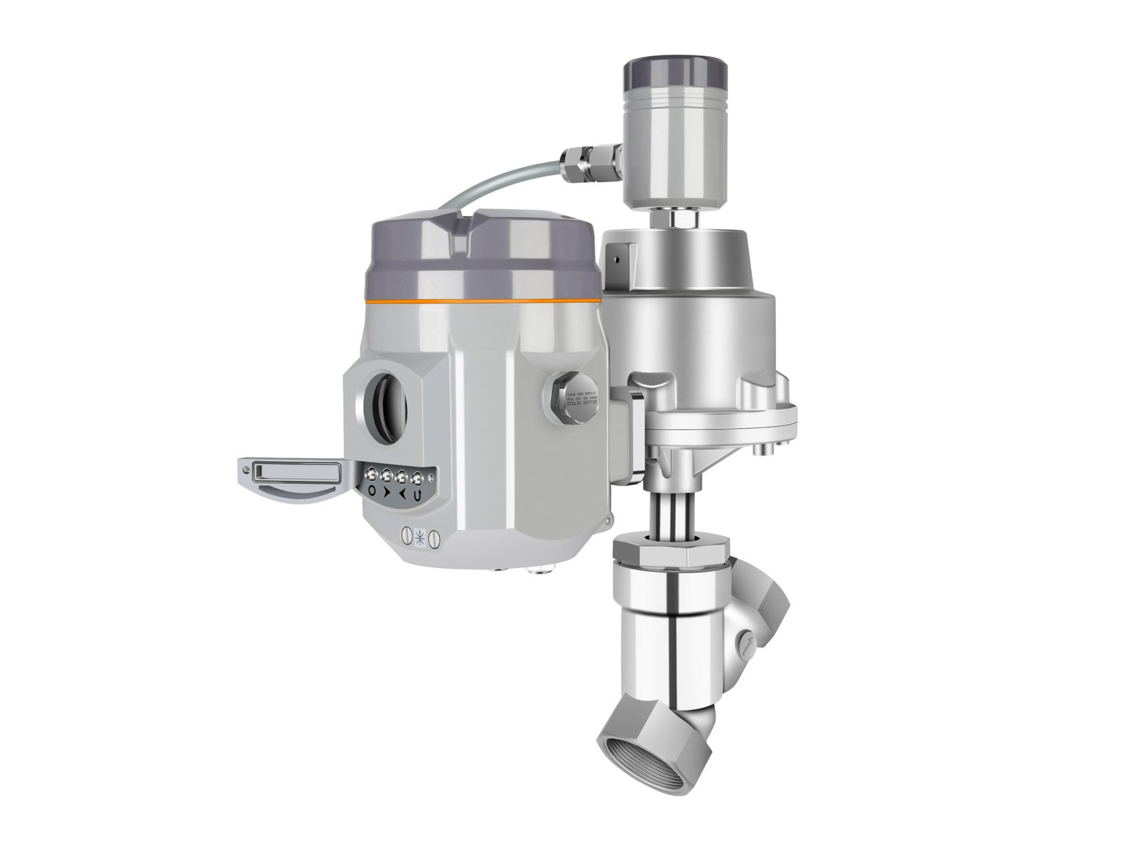
Site requirements add independent classification layers: explosion protection (Ex ia, Ex d), ingress protection (IP66/IP67), safety integrity level (SIL), temperature range, vibration resistance, and communication protocol (HART, FF, Profibus)9. None of these are just “smart” or “analog”—they are parallel requirements.
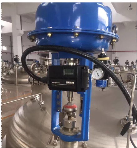
The project environment forces classification in ways that basic type lists ignore. An electro-pneumatic positioner might be available in a general-purpose plastic housing or a flameproof aluminum enclosure. Those are effectively different types for procurement. Intrinsic safety (Ex ia) and flameproof (Ex d) are not upgrades you apply to one basic unit; they are engineered variants. Then ingress protection comes in. IP66 keeps out high-pressure water. IP67 adds temporary submersion protection. If your plant has washdowns, that “smart positioner” label tells you nothing about whether it will survive.
On top of that, many projects demand functional safety. A SIL2 or SIL3 rating means the positioner has certified redundancy and self-diagnostics. I have handled inquiries where the buyer asked for “intelligent positioner with HART” and stopped there. After we talked, I discovered they needed double-acting, rotary, Ex ia, IP67, low-temperature capability to -40°C, and vibration resistance up to 4g. If they had sent a request for “HART positioner type” without those layers, the quote would have been invalid. So when someone asks me how many types of positioners exist, I answer with questions: what is your control signal, actuator motion, explosion zone, protection need, safety requirement, and temperature range? The count of types that match your exact conditions is the only number that matters. That approach avoids misapplication and lets you compare offers on an even playing field.
Conclusion
There’s no one number for positioner types. Match by signal, motion, and site needs. That way you avoid mismatches and get fair quotes.
"How Pneumatic, Analog (Electro-Pneumatic), and Digital Control ...", https://kimray.com/training/how-pneumatic-analog-electro-pneumatic-and-digital-control-valve-positioners-work. A technical source on control-valve positioners describes multiple classification bases, including input signal, actuator compatibility, and digital diagnostic capability, which supports treating the number of positioner types as context-dependent rather than fixed. Evidence role: general_support; source type: education. Supports: A technical instrumentation or control-valve source should show that positioners are classified by signal type, actuator motion, and functional features, supporting the point that there is no single universal count.. Scope note: Such a source would support the classification logic, but it may not explicitly state that no fixed number exists. ↩
"The Meaning Behind 3-15 PSI in Control Valves This pneumatic ...", https://www.facebook.com/Petroleum2015engineer/posts/the-meaning-behind-3-15-psi-in-control-valvesthis-pneumatic-pressure-range-direc/1315115887282447/. Instrumentation references commonly identify 3-15 psi as a pneumatic control signal and 4-20 mA as an analog electronic control signal, while describing smart valve positioners as microprocessor-based devices that add digital functions. Evidence role: definition; source type: education. Supports: A neutral instrumentation reference should confirm the common process-control signal ranges and the distinction between pneumatic, electro-pneumatic, and digital or smart positioners.. Scope note: The source may define the categories separately rather than present them as an exhaustive three-part classification. ↩
"Control valve - Wikipedia", https://en.wikipedia.org/wiki/Control_valve. Reference material on pneumatic process control identifies 3-15 psi as a conventional signal range, supporting the statement that pneumatic positioners commonly receive air-pressure commands in this range. Evidence role: definition; source type: encyclopedia. Supports: A reference source should verify that 3-15 psi is the conventional pneumatic signal range used in process control.. ↩
"FY400Series - HART® & 4 a 20 mA Intelligent Valve Positioner for ...", https://www.smar.com.br/en/product/fy400series-hart-4-a-20-ma-intelligent-valve-positioner-for-accurate-final-control-element-positioning. Research and technical literature on smart valve positioners describes microprocessor-based control and diagnostic functions operating alongside conventional analog current-loop signaling. Evidence role: mechanism; source type: paper. Supports: A research or technical paper should show that smart positioners incorporate microprocessors and often interface with 4-20 mA control loops.. Scope note: The statement applies to many HART or hybrid smart positioners, but not necessarily to fully digital fieldbus-only devices. ↩
"Control Valve Positioners – Azbil North America", https://us.azbil.com/category/industrial-automation/valves-positioners/. Technical literature on digital valve positioners identifies automatic calibration, diagnostic monitoring, and bidirectional communication as characteristic functions of smart positioner designs. Evidence role: general_support; source type: research. Supports: A research or institutional technical source should document common smart-positioner functions such as automatic calibration, diagnostics, and digital communication.. Scope note: Capabilities vary by device model and protocol, so the source would support the general class of functions rather than every product. ↩
"Current loop - Wikipedia", https://en.wikipedia.org/wiki/Current_loop. Protocol references describe HART as a hybrid communication method in which a digital signal is superimposed on the conventional 4-20 mA analog current loop. Evidence role: definition; source type: institution. Supports: A protocol reference should confirm that HART transmits digital information over the same wiring as a 4-20 mA analog loop.. ↩
"Fieldbus - Wikipedia", https://en.wikipedia.org/wiki/Fieldbus. Reference sources define Foundation Fieldbus and Profibus as digital fieldbus communication protocols for industrial and process automation, supporting the contrast with purely analog current-loop signaling. Evidence role: definition; source type: encyclopedia. Supports: A neutral reference should define Foundation Fieldbus and Profibus as digital fieldbus communication protocols used in industrial automation.. Scope note: The source may not specifically discuss valve positioners, but it supports the communication-protocol characterization. ↩
"Scotch Yoke vs. Rack & Pinion: Choosing the Right Actuator", https://www.hearkenvalve.com/scotch-yoke-vs-rack-pinion. Control-valve engineering references distinguish linear-stem and rotary actuator motion and describe positioner mounting and feedback arrangements as dependent on the actuator type. Evidence role: general_support; source type: education. Supports: A control-valve training or engineering reference should state that positioner selection depends on whether the actuator movement is linear or rotary.. Scope note: The source may give examples rather than prescribe every listed actuator pairing. ↩
"Understanding ATEX Codes - Measure Monitor Control", https://www.measuremonitorcontrol.com/resources/atex/atex-codes. Standards-based sources treat explosion protection, enclosure ingress protection, functional safety integrity, environmental operating limits, and communication protocols as distinct specification domains for industrial field instruments. Evidence role: expert_consensus; source type: institution. Supports: Standards and institutional references should show that explosion protection, IP ratings, SIL, environmental limits, and communication protocols are separately specified attributes for industrial instruments.. Scope note: The source would support the general specification structure for field instruments; it may not list all attributes specifically for valve positioners. ↩