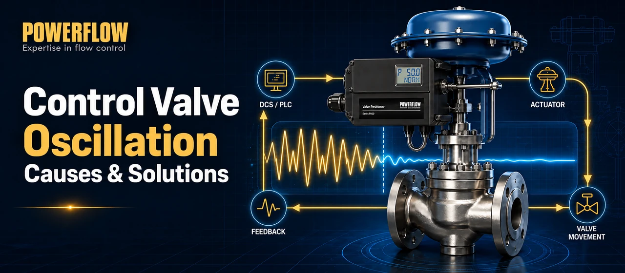
Control valve oscillation—also called hunting, cycling or valve position instability—can cause process-variable fluctuations, piping noise, accelerated packing and trim wear, and unreliable control. The valve stem may make rapid small movements, move in a repeating cycle or drift away from the requested position.
The cause is not always the valve itself. Oscillation can originate in the process-control loop, an oversized valve, mechanical friction, actuator sizing, positioner tuning, feedback installation, instrument-air supply or pneumatic leakage. Effective troubleshooting therefore requires separating the command signal, actual valve travel and process response instead of adjusting one component at random.
This guide explains the most common causes of control valve oscillation and provides a practical sequence for diagnosing and correcting them.
What Control Valve Oscillation Looks Like
Common symptoms include:
- Repeated movement of the valve stem around a fixed setpoint
- A sawtooth or cyclic valve-position trend
- A stable command signal but an unstable measured valve position
- Periodic fluctuations in flow, pressure, temperature or level
- Abnormal noise or vibration around the valve and piping
- Frequent positioner air output or continuous air consumption
Before changing PID or positioner settings, trend at least four variables at the same time:
- Process setpoint
- Process variable
- Controller output or valve command
- Actual valve position
Instrument-air pressure should also be recorded when possible. The relationship between these signals helps identify whether the disturbance begins in the process loop, the valve assembly or the pneumatic system.
Unstable Process Loop or Incorrect Controller Tuning
If the controller output, valve position and process variable all move in a repeating pattern, the oscillation may originate in the control loop rather than in the positioner. Excessive proportional gain, overly aggressive integral action, measurement noise, process dead time and interaction with another loop can all produce cycling.
How to check it:
- Compare the period of the controller-output cycle with the valve-position cycle.
- Temporarily place the loop in manual mode, if the process and site procedure permit it.
- Apply a small, controlled output change and observe whether the valve settles.
- Check the transmitter signal for noise or intermittent faults.
- Review recent changes to PID tuning, production rate or upstream equipment.
Corrective actions:
- Retune the process controller using a suitable plant procedure.
- Filter measurement noise only when justified; excessive filtering adds delay.
- Investigate interacting loops and upstream disturbances.
- Confirm that the valve is correctly sized and operating within a controllable range before finalizing PID settings.
The valve, actuator and positioner should be evaluated as part of the complete control loop. Positioner adjustments alone cannot correct an unstable process design.
Oversized Control Valve and Unstable Low-Travel Operation
An oversized control valve often operates very close to its seat during normal production. In this region, a small change in valve travel may cause a disproportionately large change in flow. The resulting high installed gain can make the loop difficult to control and may cause hunting, especially at low load.
Low travel can also expose the trim to high local velocity, erosion, noise, flashing or cavitation, depending on the fluid and pressure conditions. However, no single travel range—such as 20% to 80%—is universally correct for every valve. Acceptable travel depends on valve style, trim characteristic, rangeability, pressure drop and the required minimum and maximum flow.
How to check it:
- Review the valve travel at minimum, normal and maximum operating conditions.
- Recalculate the required Cv or Kv using actual process data.
- Examine the installed flow characteristic and installed gain, not only the nominal valve size.
- Check for cavitation, flashing, choked flow or excessive aerodynamic noise.
Corrective actions:
- Select a smaller valve or reduced-capacity trim when the existing valve is oversized.
- Use an appropriate inherent characteristic for the installed system.
- Consider split-range or parallel-valve arrangements when the required operating range is exceptionally wide.
- Verify the revised selection with the valve manufacturer's sizing software.
Valve Stiction, Packing Friction and Mechanical Binding
Stiction occurs when static friction prevents the valve from moving until the actuator force becomes large enough to break it free. The valve then jumps past the desired position, stops and repeats the cycle. Tight packing, stem corrosion, worn guides, contamination, misalignment, damaged trim and rotary-shaft backlash can all contribute to deadband and poor resolution.
Typical signs include:
- The command signal changes while the valve position remains stationary.
- The valve suddenly jumps after the command has accumulated.
- The position trend forms a stick-slip or sawtooth pattern.
- The problem is more obvious when the valve reverses direction.
Corrective actions:
- Inspect the stem, shaft, packing, guides, bearings, linkage and trim.
- Adjust packing only according to the valve manufacturer's procedure and leakage requirements.
- Remove deposits and foreign material from the valve body.
- Correct actuator-to-valve alignment.
- Replace worn guides, seals, packing or trim as required.
- Perform an appropriate travel, step-response or diagnostic test after maintenance.
The Emerson Control Valve Handbook provides additional information about friction, deadband and the dynamic performance of valve assemblies.
Insufficient Actuator Thrust or Torque
The actuator must overcome valve friction, packing load, fluid forces and the required shutoff force throughout the specified operating range. An undersized actuator may be unable to hold the requested position when differential pressure changes.
For spring-return actuators, an incorrectly selected or fatigued spring can also affect stability and fail action. Double-acting actuators do not necessarily use a return spring, so their performance should be assessed using available pneumatic torque or thrust, friction, supply pressure and any required safety accessories.
Corrective actions:
- Recalculate actuator thrust or torque at minimum available supply pressure.
- Include maximum differential pressure, unbalanced force, friction and shutoff requirements.
- Inspect spring condition where a spring-return actuator is used.
- Check actuator seals, bearings and alignment.
- Replace or resize the actuator if the available margin is insufficient.
Valve Positioner Tuning Is Too Aggressive or Incorrect
A positioner forms a fast local position-control loop around the actuator and valve. If its gain, damping or dynamic parameters do not match the actuator volume, valve friction and pneumatic accessories, the valve can overshoot and repeatedly correct itself.
Sensitivity, gain, damping and deadband are related but not interchangeable terms. Their names and functions vary by manufacturer. Increasing gain can improve response and reduce apparent deadband, but excessive gain may destabilize the valve assembly. Increasing deadband may reduce unnecessary corrections, but too much deadband reduces positioning accuracy.
Corrective actions:
- Verify that the positioner is configured for the correct actuator type, travel direction and single- or double-acting output.
- Run the manufacturer's initialization or auto-calibration procedure under controlled conditions.
- Use the recommended tuning class for the actuator size and type.
- Reduce aggressiveness or increase damping in small steps when the valve overshoots.
- After each change, perform a step test and confirm settling time, overshoot and steady-state stability.
Auto-calibration may stroke the valve through a significant part of its travel. Follow the plant permit procedure and the positioner manual; do not initiate it on an operating process unless the procedure is known to be safe.
Incorrect Positioner Installation or Feedback Problems
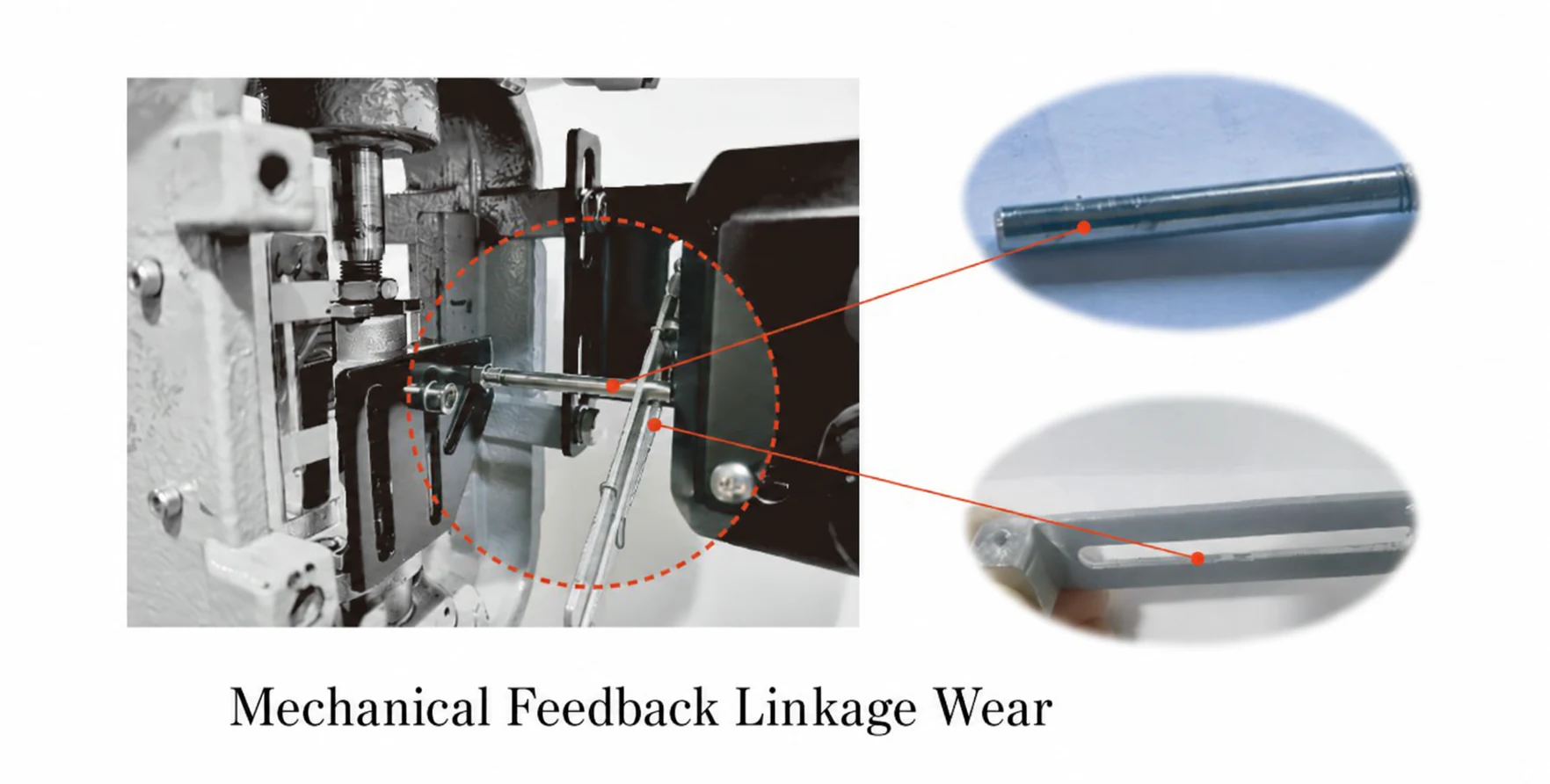
Loose feedback arms, excessive linkage clearance, an incorrect lever angle, poor bracket rigidity or an incorrectly positioned magnetic target can distort the measured valve position. The positioner then reacts to an inaccurate or delayed feedback signal.
Corrective actions:
- Tighten brackets, feedback arms and fasteners.
- Confirm the mounting geometry and usable feedback range.
- Check that the linkage moves freely through the full stroke without binding.
- Verify magnet or target alignment on non-contact feedback systems.
- Recalibrate zero, span and travel after correcting the installation.
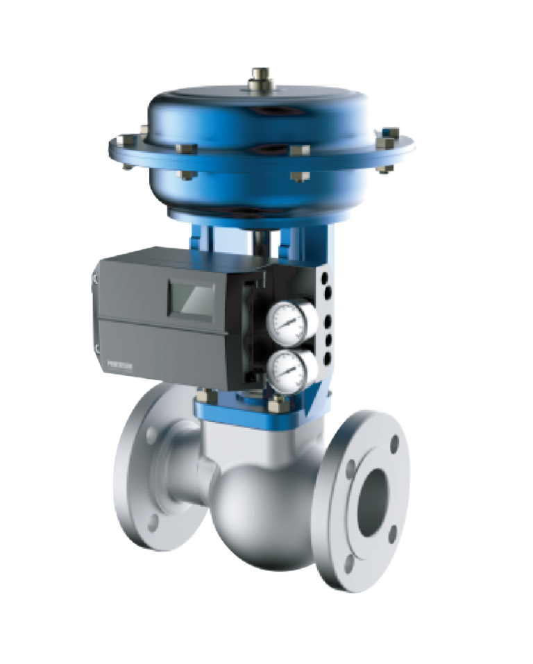
Non-contact feedback can remove wear points associated with a mechanical contact sensor, but correct mounting, alignment and commissioning are still essential. The POWERFLOW IP7000 non-contact smart valve positioner uses magnetic Hall sensing and is designed for linear and rotary pneumatic actuators.
Unstable Instrument-Air Supply
Low supply pressure, inadequate air capacity, a malfunctioning filter regulator, undersized tubing, contamination or compressor cycling can change actuator force and positioner dynamics. If several valves oscillate at the same time, a common instrument-air problem should be investigated early.
External volume boosters require particular attention. Incorrect bypass adjustment, excessive booster sensitivity or a damaged diaphragm can cause the actuator pressure to cycle instead of settling.
Corrective actions:
- Measure supply pressure dynamically while the valve is moving, not only at steady state.
- Compare available pressure and flow capacity with the actuator and positioner requirements.
- Inspect the filter regulator, booster, tubing, fittings and air-set drain.
- Remove water, oil and particles from the pneumatic system.
- Check tubing diameter and length for excessive pressure drop.
- Adjust booster bypass only according to the manufacturer's procedure.
For large actuators, a properly selected volume booster can improve stroking speed, but it must be tuned so that fast response does not create instability. Emerson describes this function in its overview of the Fisher VBL volume booster.
Pneumatic Leakage or Actuator Seal Failure
A damaged diaphragm, worn piston seal, leaking O-ring, cracked tube or loose fitting allows pressure to escape from the actuator circuit. The positioner repeatedly supplies air to compensate, which can produce continuous small corrections, drift or failure to reach the requested position.
Corrective actions:
- Conduct a leak test using an approved leak-detection method.
- Isolate and pressure-test the actuator chambers when permitted.
- Replace damaged diaphragms, seals, tubing and fittings.
- Confirm the positioner's steady-state air consumption against its specification.
- Recalibrate and perform a full functional test after repairs.
Pipeline Vibration, Resonance and Poor Mounting
Mechanical vibration can loosen feedback hardware, damage tubing and connectors, and introduce noise into the measured position. In severe applications, mounting a positioner directly on the actuator may expose its electronics and pneumatic components to continuous vibration.
Corrective actions:
- Identify the vibration source instead of treating only the symptom.
- Inspect pipe supports, valve installation and bracket rigidity.
- Check the assembly for a mechanical resonance near the excitation frequency.
- Use remote-mounted or split-mounted feedback where the product design and application permit it.
- Protect feedback cables and pneumatic tubing from movement and abrasion.
POWERFLOW has documented a remote-mounted IP6000 application on a DN350 control valve where the positioner body was installed away from a high-vibration valve assembly. The IP6000 smart valve positioner supports remote and split-type mounting options for suitable applications.
Field Examples
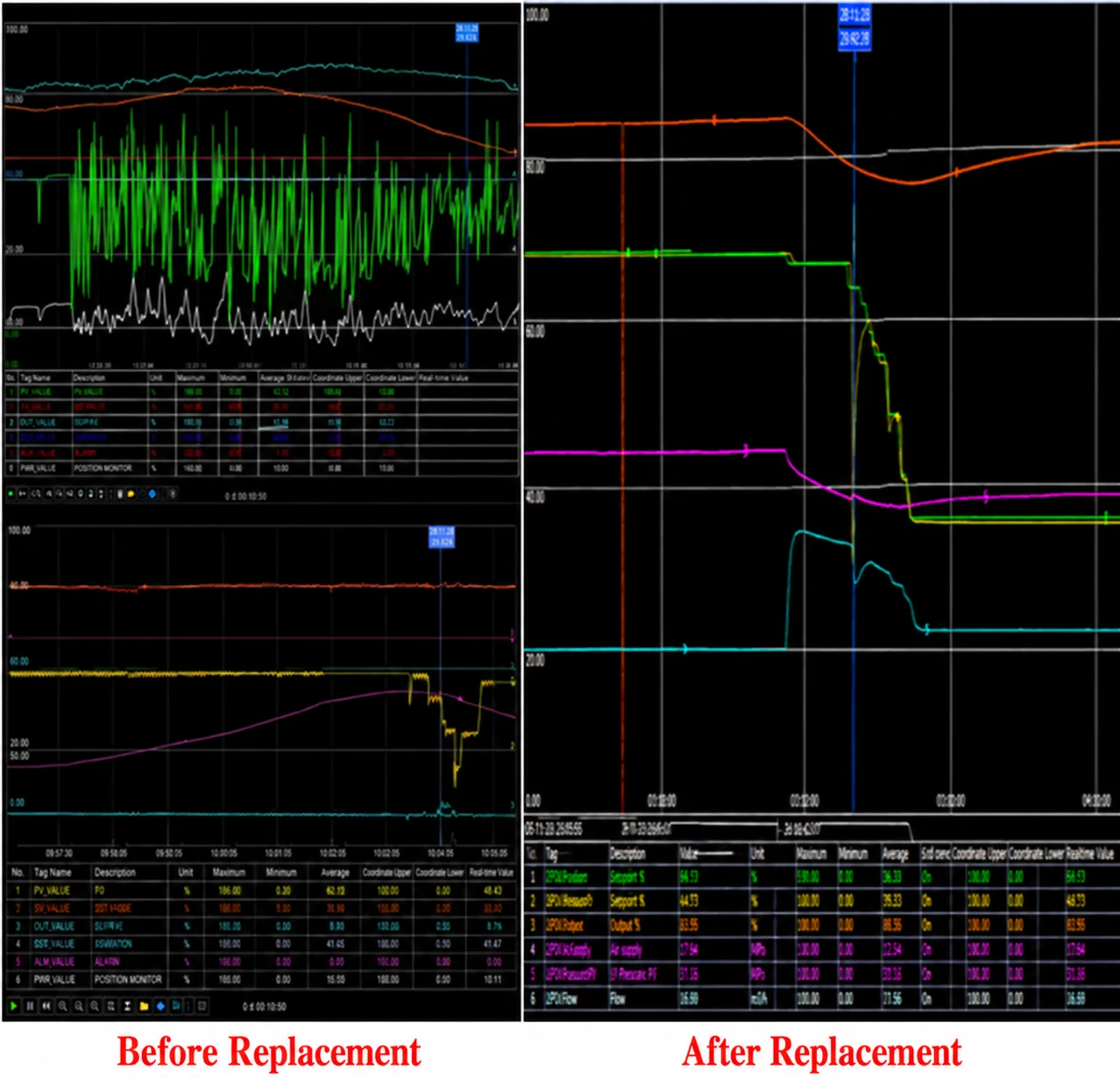
Low-Temperature Positioner Replacement
At one overseas installation, the valve command and position feedback did not track consistently in a low-temperature environment. Site investigation indicated that the original positioner had not been validated for the ambient condition. After it was replaced with a configuration suitable for the required low-temperature range, the command and feedback trends became stable.
This example shows why environmental ratings must be verified for the exact model and configuration. Temperature limits stated on a general product family page should not replace the applicable datasheet, certificate and installation manual.
Loose Feedback Retaining Clip
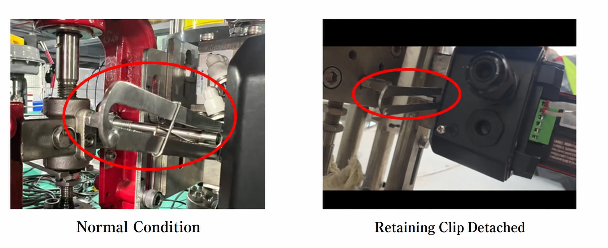
In another application, the valve reached a 70% command but the indicated position slowly increased until the positioner corrected it back to 70%. The cycle then repeated. Inspection found that a retaining clip in the mechanical feedback assembly was missing, preventing the feedback pin and lever from remaining securely engaged. Reinstalling the clip restored reliable feedback and eliminated the repeated correction.
This case illustrates why installation hardware should be checked before changing tuning parameters.
A Practical Troubleshooting Sequence
Use a structured sequence to avoid unnecessary adjustments:
- Confirm the symptom. Trend command, actual position, process variable and air pressure.
- Separate process-loop and valve behavior. Determine whether the command is cycling or the valve is moving independently of a stable command.
- Check instrument air and leakage. Verify dynamic pressure, capacity, filtration, tubing and actuator sealing.
- Inspect installation and feedback. Check brackets, linkage, target alignment and calibration.
- Review positioner configuration. Confirm actuator mode, travel direction, tuning and booster settings.
- Check valve and actuator mechanics. Look for stiction, binding, backlash, misalignment and inadequate thrust or torque.
- Review sizing and process conditions. Confirm Cv or Kv, installed gain, pressure drop and minimum-to-maximum load range.
- Change one variable at a time. Record the result of every adjustment and restore the approved configuration if performance becomes worse.
The commonly used rule “check accessories before dismantling the valve” is efficient, but it should not replace evaluation of the process controller. PID tuning, process disturbances and valve sizing can all contribute to hunting.
Choosing a Positioner for Difficult Applications
The positioner should be selected as part of the complete valve assembly. Important factors include:
- Linear or rotary valve motion
- Single-acting or double-acting actuator
- Actuator volume and required stroking speed
- 4–20 mA, HART or other communication requirements
- Ambient temperature and vibration level
- Hazardous-area classification
- Required enclosure protection
- Standard, remote or split mounting
- Diagnostic and maintenance requirements
The POWERFLOW valve positioner range includes standard, remote-mounted and non-contact-feedback options for different pneumatic valve applications. Final selection should always be based on the exact valve, actuator, process conditions and applicable product documentation.
Frequently Asked Questions
Can incorrect PID tuning make a control valve oscillate?
Yes. Aggressive proportional or integral settings, process dead time, measurement noise and interacting loops can produce a repeating controller output. Always compare the controller output with actual valve position before assuming the positioner is responsible.
How can I tell whether valve stiction is causing the oscillation?
With stiction, the command usually changes while the valve remains stationary. The valve then breaks free and jumps past the requested position. A trend of command and actual position, combined with a controlled step or diagnostic test, can help confirm this behavior.
Should I increase the positioner deadband to stop hunting?
Not automatically. A small increase may reduce unnecessary corrections in some installations, but excessive deadband reduces accuracy. First check mechanical friction, air supply, feedback installation and actuator sizing, then follow the positioner manufacturer's tuning procedure.
Why does a valve oscillate even when the command signal is stable?
Likely causes include positioner tuning, unstable air supply, pneumatic leakage, feedback problems, stiction, insufficient actuator force or mechanical vibration. Compare actual valve position and actuator pressure with the stable command to narrow the cause.
Conclusion
Control valve oscillation is a symptom, not a single fault. The fastest diagnosis comes from determining where the cycle begins: the process controller, the valve and actuator, the positioner feedback loop or the pneumatic supply.
Start with trends and non-invasive checks. Confirm signal behavior, instrument-air stability, leakage, installation and positioner configuration before dismantling the valve. If those checks do not explain the problem, evaluate stiction, actuator sizing, valve sizing and the installed process characteristic.
If you need help evaluating a pneumatic control valve application, contact POWERFLOW with the valve type, actuator model, operating pressure, control signal, current positioner and a trend showing command versus actual position.