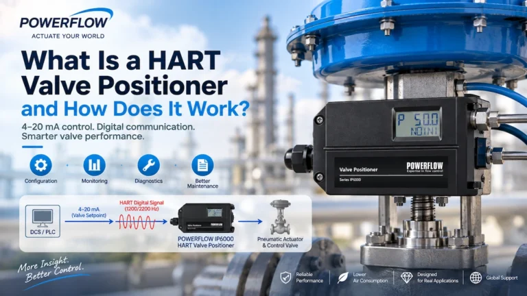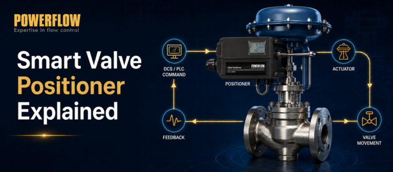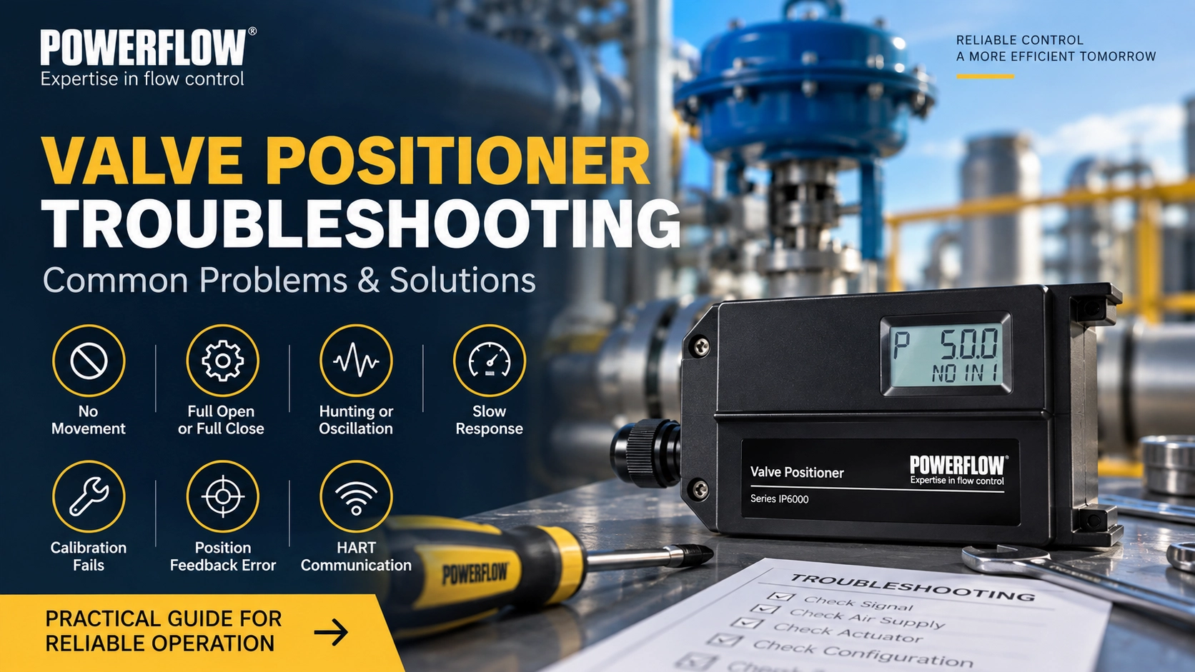
Valve positioners are critical to accurate and stable control valve operation. However, when a valve does not move, oscillates around the setpoint, responds too slowly, fails calibration, or loses communication, the positioner itself is not always the root cause.
Many field problems are actually related to the control signal, instrument air, actuator, valve mechanics, feedback linkage, installation, or configuration.
This guide provides a practical approach to valve positioner troubleshooting, based on common field issues and POWERFLOW service experience. It covers seven typical symptoms, explains what to check first, and provides a step-by-step troubleshooting procedure to help engineers identify the root cause more efficiently.
Safety note: Always follow the applicable plant safety procedures before inspecting, disconnecting, or servicing a control valve, actuator, or valve positioner. In hazardous areas, work must comply with the applicable explosion-protection requirements and site procedures.
Quick Valve Positioner Troubleshooting Guide
The table below provides a quick starting point before going into detailed troubleshooting.
| Problem | Possible Causes | First Checks |
|---|---|---|
| Valve or positioner does not move | Signal/power issue, air supply problem, wiring error, actuator or valve blockage, incomplete calibration, internal fault | Check control signal, wiring, air supply, manual mode, actuator and valve |
| Valve only fully opens or fully closes | Incorrect calibration, wrong action setting, feedback out of range, air leakage | Check configuration, feedback linkage and auto-calibration |
| Valve hunting or oscillation | Deadband too small, valve stiction, linkage looseness, unstable air pressure, actuator leakage, booster setting, process disturbance | Check tuning parameters, mechanical linkage, air supply and DCS trend |
| Valve responds too slowly | Insufficient pneumatic capacity, restricted tubing, leakage, large actuator volume, mechanical friction | Compare positioner output pressure with actual valve movement |
| Auto-calibration fails | Insufficient air supply, mechanical blockage, incorrect feedback installation, excessive friction, unstable signal | Confirm full valve travel, air supply, feedback linkage and actuator condition |
| Position feedback does not match actual valve position | Loose linkage, installation offset, incorrect calibration, sensor interference or parameter error | Inspect feedback mechanism and repeat calibration |
| HART communication fails | Loop/load issue, wiring problem, incompatible barrier or isolator, excessive cable capacitance, interference, device-description issue | Check the loop, wiring, HART-compatible equipment and host configuration |
1. Valve or Positioner Does Not Move
One of the most common field complaints is:
“The control signal changes, but the valve does not move.”
Do not immediately assume that the valve positioner is defective. Troubleshooting should begin with the basic electrical and pneumatic conditions.
Possible Causes
Common causes include:
- No valid control signal or insufficient electrical supply
- Incorrect wiring or loose terminals
- No instrument air or insufficient supply pressure
- Blocked or restricted pneumatic tubing
- Actuator or valve mechanically stuck
- Positioner left in local manual mode
- Auto-calibration or initialization not completed
- Feedback mechanism incorrectly installed
- Internal pneumatic pilot module fault
- Internal electronic or sensor fault
Step 1: Check the Control Signal and Wiring
Measure the actual control signal at the positioner terminals.
For a typical 4–20 mA control loop, confirm that the signal changes correctly when the command from the DCS or PLC changes.
Also check:
- Terminal polarity
- Loose or oxidized terminals
- Damaged wiring
- Cable continuity
- Loop voltage under actual operating conditions
- Whether any barrier, isolator, or other loop device is affecting the signal
Always refer to the applicable positioner datasheet for the required electrical conditions.
Step 2: Check the Instrument Air
Confirm that clean, dry instrument air reaches the positioner inlet.
Check:
- Supply pressure
- Filter condition
- Tubing for blockage or restriction
- Water or contamination in the air line
- Pneumatic connections
- Leakage at fittings and tubing
The required air pressure depends on the actuator and valve package. Do not rely on a generic pressure value; confirm the actuator and positioner requirements for the specific application.
Step 3: Test the Positioner in Local Manual Mode
For POWERFLOW IP6000, IP6500 and IP7000 series positioners, local manual operation can help separate a signal/configuration problem from a pneumatic or hardware problem.
If the positioner is switched to local manual mode:
If there is still no output pressure:
Prioritize checking:
- Instrument air supply
- Internal pneumatic passages
- Pilot/piezoelectric pneumatic module
- Internal pneumatic contamination or damage
If the valve can be driven normally in manual mode:
The problem is more likely related to:
- Input signal
- Configuration
- Calibration
- Feedback mechanism
- Control system
This simple test can significantly narrow the troubleshooting range.
2. Valve Only Fully Opens or Fully Closes
Another common symptom is that the valve moves, but only between the fully open and fully closed positions. It cannot reliably stop at intermediate positions.
Possible Causes
Check for:
- Incorrect zero or span setting
- Wrong direct/reverse action configuration
- Feedback linkage installed incorrectly
- Feedback mechanism outside its effective range
- Severe pneumatic leakage
- Insufficient actuator thrust
- Abnormal or limited DCS output signal
- Calibration not completed correctly
Troubleshooting Steps
First, compare the positioner's displayed input or setpoint with the actual signal from the control system.
Then check the feedback mechanism.
The feedback lever or sensor must operate within its intended measurement range throughout the complete valve stroke.
If the feedback mechanism reaches its limit too early or does not cover enough travel, the positioner may not be able to determine the actual valve position correctly.
Next:
- Verify the zero/span configuration.
- Confirm direct or reverse action.
- Inspect the feedback linkage.
- Check for pneumatic leakage.
- Run auto-calibration again.
POWERFLOW Tip: After installation or mechanical adjustment, perform the applicable auto-calibration procedure instead of relying only on manual zero adjustment.
3. Valve Hunting or Oscillation
Valve hunting occurs when the valve repeatedly moves back and forth around the target position instead of settling steadily at the setpoint.
This can reduce control stability, increase air consumption, and accelerate wear of the valve, actuator and linkage.
Common Causes of Valve Hunting
Possible causes include:
- Deadband set too small
- Excessive valve packing friction or stiction
- Loose or worn feedback linkage
- Unstable instrument air pressure
- Actuator diaphragm or cylinder leakage
- Excessive volume booster gain
- Pneumatic restriction
- Process-loop disturbance
- Incorrect tuning parameters
Troubleshooting Valve Hunting
Start by checking whether the oscillation originates from the valve assembly or from the upstream control loop.
Step 1. Check the DCS Setpoint Trend
If the command signal itself is continuously fluctuating, the positioner may simply be following the command.
In this case, investigate the process-control loop before changing the positioner settings.
Step 2. Check Mechanical Friction
Valve stiction is a common source of oscillation.
When friction prevents smooth movement, the positioner continues increasing its output until the valve suddenly breaks free. The valve may then overshoot the target position, causing the positioner to correct in the opposite direction.
Inspect:
- Valve packing
- Stem or shaft movement
- Actuator condition
- Mechanical alignment
Step 3. Inspect the Feedback Linkage
Loose joints, excessive clearance, worn components, or incorrect installation can introduce unstable feedback.
Tighten the linkage and confirm that the feedback mechanism moves smoothly throughout the full stroke.
Step 4. Check the Air Supply
Unstable supply pressure or restricted pneumatic lines can also produce unstable valve movement.
Inspect the filter, regulator, tubing and fittings.
Step 5. Check Volume Booster Settings
If a volume booster is installed, excessive booster sensitivity or gain can cause hunting.
Adjust the booster according to the actuator and control requirements rather than assuming that maximum pneumatic response is always better.
For applications where mechanical feedback wear or severe vibration is a recurring concern, a non-contact feedback solution may also be worth considering.
4. Valve Responds Too Slowly
A slow valve response does not automatically mean that the positioner is too slow.
The key is to compare the positioner output pressure response with the actual actuator and valve movement.
If Output Pressure Changes Quickly but the Valve Moves Slowly
The problem is more likely related to:
- Large actuator volume
- Restricted pneumatic tubing
- Mechanical friction
- Valve stiction
- Actuator problems
- Incorrect pneumatic sizing
If Output Pressure Also Changes Slowly
Prioritize checking:
- Instrument air supply
- Positioner pneumatic output capacity
- Filter blockage
- Restricted internal pneumatic passages
- Tubing restriction
- Pilot pneumatic module condition
If the Valve Is Slow and There Is Obvious Air Leakage
Inspect:
- Pneumatic tubing
- Fittings
- Actuator diaphragm or cylinder
- Seals
- Positioner pneumatic connections
A suitable leak-detection method can be used on permitted pneumatic connections to identify leakage points.
When Is a Volume Booster Needed?
A volume booster may be required when:
- The actuator volume is large
- Fast stroke time is required
- The positioner's pneumatic output capacity is insufficient for the required dynamic response
- Long or restrictive tubing limits air flow
However, adding a booster is not automatically the correct solution.
Pneumatic sizing and dynamic testing should be used to confirm whether additional flow capacity is actually required.
5. Auto-Calibration Fails
Modern smart valve positioners typically use an initialization or auto-calibration procedure to identify the valve travel, direction and control characteristics.
When calibration fails, the positioner is often reacting to another problem in the valve package rather than experiencing an electronic failure itself.
Common Causes
Check for:
- Insufficient instrument air pressure
- Actuator unable to complete full travel
- Mechanical blockage
- Excessive valve friction
- Incorrect feedback linkage installation
- Feedback mechanism outside its usable range
- Unstable input signal
- Incorrect parameter configuration
- Pneumatic leakage
Troubleshooting Procedure
Before repeating calibration:
a. Confirm that the valve can physically travel through the required range. b. Confirm stable instrument air. c. Inspect the actuator and valve for mechanical restriction. d. Check the feedback linkage or sensor installation. e. Confirm that the positioner configuration matches the actuator. f. Eliminate significant pneumatic leakage. g. Run auto-calibration again.
Do not repeatedly restart auto-calibration without first identifying why the previous attempt failed.
6. Position Feedback Does Not Match the Actual Valve Position
Sometimes the control valve reaches one physical position while the positioner display or transmitted feedback indicates another.
This may be caused by the feedback mechanism rather than the control signal itself.
Possible Causes
- Loose feedback linkage
- Incorrect feedback lever geometry
- Incorrect installation position
- Mechanical play or wear
- Calibration drift
- Feedback sensor interference
- Incorrect travel configuration
- Parameter setting error
Troubleshooting Steps
First, physically confirm the actual valve position.
Then compare:
- Actual valve travel
- Positioner display
- DCS position indication
- Optional 4–20 mA position feedback, if installed
Inspect the feedback linkage throughout the entire valve stroke.
The mechanism should move smoothly and remain within its effective range without binding, excessive clearance, or reaching a mechanical limit prematurely.
After correcting the mechanical installation, perform calibration again.
For applications exposed to severe vibration or repeated mechanical-feedback wear, a non-contact position feedback design may reduce problems associated with mechanical linkage wear.
7. HART Communication Fails
A HART-enabled valve positioner may continue controlling the valve through the 4–20 mA loop even when HART communication is unavailable.
Therefore, a HART communication failure should be diagnosed separately from a valve-control failure.
Common Causes
Possible causes include:
- Insufficient loop impedance
- Wiring or connection problem
- Incorrect communicator connection
- Incompatible barrier or isolator
- Excessive cable capacitance
- Strong electrical interference
- Grounding or shielding problems
- Missing or incompatible DD/EDD/DTM files
- Host-system configuration issue
- Multiple devices or loop components affecting communication
What to Check
Verify:
a. The 4–20 mA loop is operating normally. b. Loop conditions meet the HART communication requirements. c. The handheld communicator or modem is connected correctly. d. Barriers and isolators are HART compatible. e. Cable and grounding practices are appropriate. f. The host system has the correct device description or integration files where required.
For a detailed explanation of how HART digital communication works together with the 4–20 mA signal, see our guide:
What Is a HART Valve Positioner and How Does It Work?
A Step-by-Step Valve Positioner Troubleshooting Procedure
When a valve positioner “does not work,” troubleshooting is more efficient when performed in a fixed sequence.
Avoid changing multiple parameters at the same time. Start with the most basic conditions and progressively isolate the problem.
Step 1: Check the Signal and Electrical Conditions
Confirm:
- Input signal
- Loop voltage
- Wiring
- Terminal connections
- Polarity
- Barriers or isolators, if used
Step 2: Check the Instrument Air
Confirm:
- Supply pressure
- Air quality
- Filter condition
- Pneumatic tubing
- Leakage
- Restrictions
Step 3: Test Local Manual Operation
Use local manual operation where supported.
Determine whether the positioner can generate output pressure and drive the actuator independently of the normal control signal.
This is one of the most useful ways to separate an electrical/configuration problem from a pneumatic or mechanical problem.
Step 4: Check the Actuator and Valve
Confirm:
- Full actuator travel
- Valve stem or shaft movement
- Mechanical friction
- Valve stiction
- Actuator leakage
- Mechanical blockage
Step 5: Check Configuration and Calibration
Verify:
- Direct/reverse action
- Travel settings
- Feedback configuration
- Deadband
- Relevant control parameters
- Auto-calibration status
Step 6: Check the Positioner Hardware
If all external conditions are normal but the fault remains, inspect the positioner according to the manufacturer's service procedure.
Possible internal problems may include:
- Pneumatic pilot module damage
- Contaminated pneumatic passages
- Feedback sensor fault
- Electronic component damage
- Internal moisture or corrosion
The general principle is:
Signal → Air Supply → Manual Mode → Actuator/Valve → Configuration/Calibration → Positioner Hardware
This sequence prevents unnecessary disassembly and helps identify the actual source of the problem more efficiently.
When Should You Stop Troubleshooting and Contact the Manufacturer?
Not every field problem should be handled by further on-site disassembly.
Stop troubleshooting and contact the manufacturer or qualified service personnel when:
- The explosion-proof enclosure is damaged
- Water has entered the positioner
- Internal corrosion is visible
- Electronic components show signs of burning or overheating
- The pneumatic module continuously vents abnormally
- Internal components appear physically damaged
- A hazardous-area device requires internal repair without appropriate authorization or facilities
- The fault remains after the external signal, air supply, actuator, valve, installation and configuration have been verified
For explosion-protected equipment, maintaining the integrity of the certified enclosure and installation is especially important.
Do not modify certified structural components or perform unauthorized internal repairs that may affect explosion-protection performance.
Real POWERFLOW Valve Positioner Troubleshooting Cases
The following examples are based on actual POWERFLOW after-sales troubleshooting cases. They demonstrate why identifying the root cause is more useful than simply replacing or recalibrating the positioner.
Case 1: Moisture and Contamination Caused Internal Pneumatic Failure
Symptom
A POWERFLOW IP6000 valve positioner powered on normally.
The display operated normally, the 4–20 mA control signal was present, and the external air supply pressure appeared normal.
However:
- The valve did not move.
- Switching the positioner to local manual mode still produced no effective pneumatic output.
Because the problem remained in manual mode, the investigation moved away from the DCS signal and configuration and focused on the pneumatic section of the positioner.
Inspection
After inspection, moisture and contamination were found inside the pneumatic section.
The compressed-air quality at the installation site had allowed water and contaminants to enter the positioner, eventually damaging the piezoelectric pneumatic module.
Root Cause
Poor instrument-air quality caused internal contamination and damage to the pneumatic pilot module.
Corrective Action
The damaged pneumatic component was serviced or replaced as appropriate, and the customer was advised to check the upstream instrument-air system, filtration and moisture control before returning the positioner to service.
This case illustrates an important troubleshooting principle:
A normal display and a valid 4–20 mA signal do not necessarily mean that the pneumatic section is functioning correctly.
If a positioner cannot generate output pressure even in local manual mode, the air supply and internal pneumatic stage should be checked before focusing on the control system.
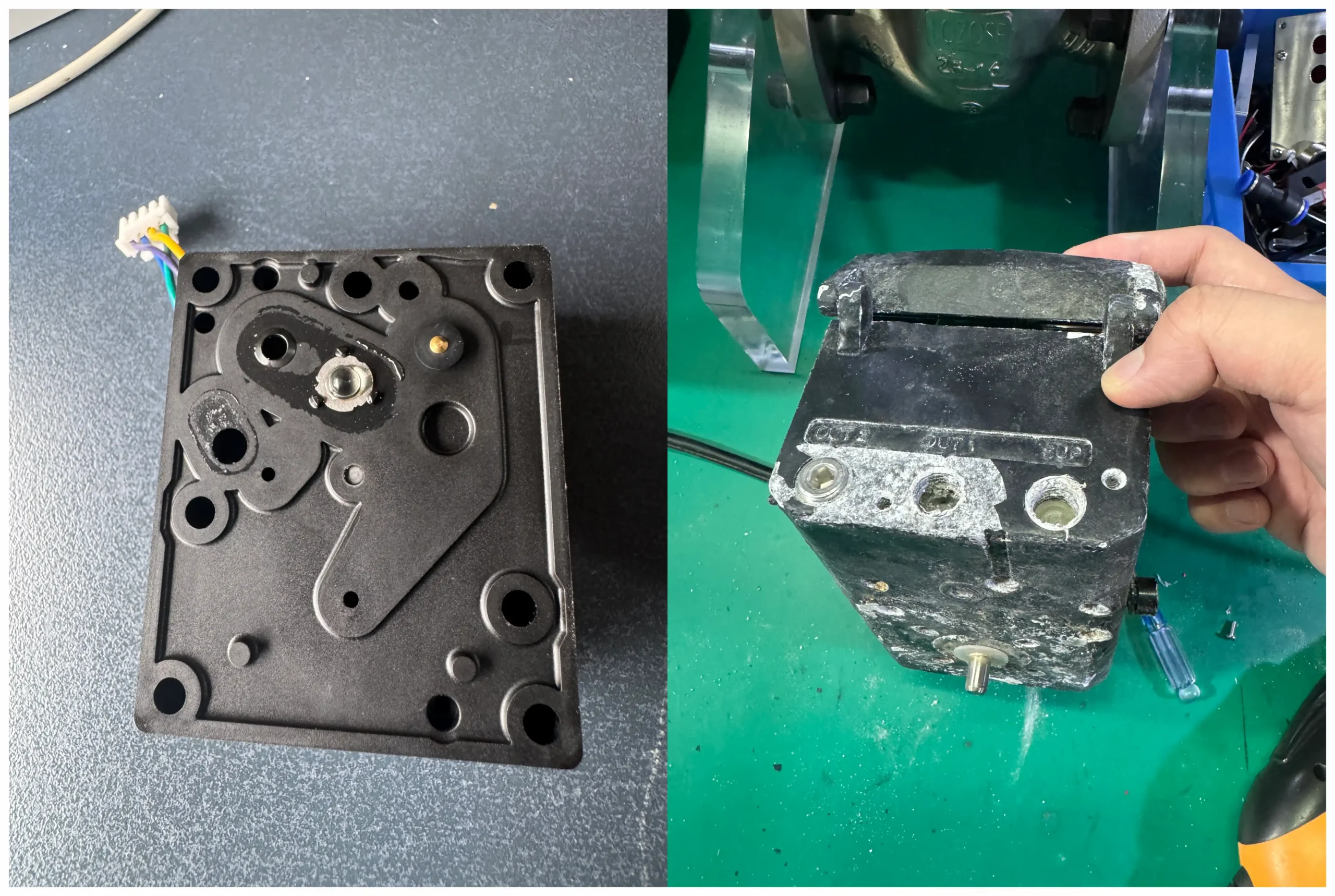 Moisture and contamination found during inspection of a returned valve positioner.
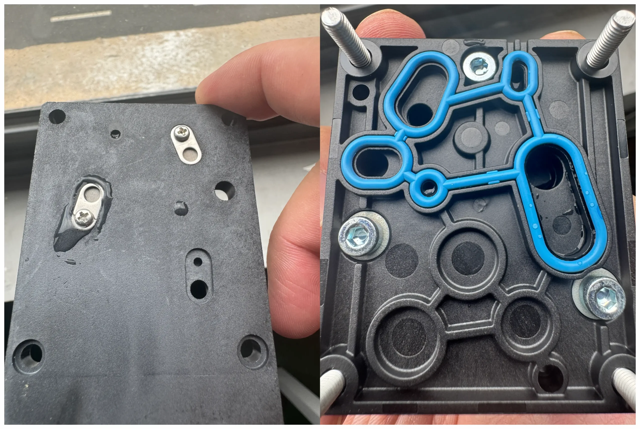 Internal pneumatic section inspected after moisture ingress and contamination.
Case 2: ERR 1 During Auto-Calibration
Symptom
During commissioning, the valve positioner displayed:
ERR 1
The error appeared during the auto-calibration procedure and calibration could not be completed normally.
Troubleshooting
Instead of treating the error code as immediate evidence of an electronic failure, the complete valve package was checked.
The troubleshooting process included:
- Instrument air supply
- Pneumatic tubing and connections
- Actuator movement
- Valve travel
- Feedback mechanism
- Mechanical installation
- Leakage points
A pneumatic leakage point was identified during the inspection.
The leakage prevented the actuator and positioner from completing the calibration sequence under stable pneumatic conditions.
Root Cause
Pneumatic leakage in the valve/actuator installation interfered with the auto-calibration process.
Corrective Action
The leakage point was located and corrected.
After the pneumatic system was restored to proper condition, the calibration procedure could be performed again.
This case demonstrates another important principle:
A calibration error does not automatically mean that the valve positioner itself is defective.
The positioner, actuator, valve, pneumatic tubing and air supply operate as one control package. Problems elsewhere in the package can appear as a positioner calibration error.
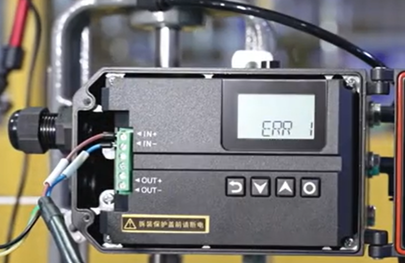
ERR 1 displayed during an actual POWERFLOW valve positioner commissioning and troubleshooting case.
Frequently Asked Questions About Valve Positioner Troubleshooting
Why does my valve positioner have power but the valve does not move?
A powered display only confirms that part of the electrical system is operating. The problem may still be related to instrument air, pneumatic output, actuator blockage, valve stiction, calibration, feedback, or an internal pneumatic component.
Check the control signal and air supply first, then test local manual operation where supported.
Why is my control valve hunting?
Common causes include valve stiction, excessive mechanical clearance, unstable air pressure, actuator leakage, overly sensitive tuning, inappropriate volume booster settings, or an unstable upstream control loop.
Check the DCS trend before assuming the positioner is the source of the oscillation.
Why does valve positioner auto-calibration fail?
Auto-calibration can fail when the actuator cannot complete its required travel, instrument air is insufficient, the feedback mechanism is incorrectly installed, mechanical friction is excessive, pneumatic leakage exists, or the positioner configuration does not match the actuator.
Why is the valve moving slowly?
Compare the positioner's pneumatic output with the actual valve movement.
If output pressure changes quickly but the valve moves slowly, investigate actuator volume, pneumatic tubing, mechanical friction and valve stiction.
If output pressure itself changes slowly, investigate the air supply, pneumatic restrictions and positioner output stage.
Can a HART communication problem stop the valve from working?
In a typical point-to-point 4–20 mA + HART application, loss of HART communication does not necessarily stop basic valve positioning because the analog 4–20 mA channel carries the control setpoint.
HART communication is primarily used for configuration, status information, diagnostics and device management.
Should I disassemble a valve positioner if troubleshooting does not solve the problem?
Not necessarily.
If the external signal, air supply, actuator, valve, installation and configuration have already been verified, contact the manufacturer before further internal disassembly—especially for explosion-protected equipment, water ingress, corrosion, burned components, or suspected internal pneumatic/electronic damage.
Preventing Common Valve Positioner Problems
Many valve positioner failures can be reduced through correct installation and routine maintenance.
Recommended practices include:
- Use clean, dry instrument air that meets the equipment requirements.
- Maintain upstream filters and regulators.
- Prevent water and contaminants from entering pneumatic lines.
- Install feedback linkages correctly and avoid excessive mechanical clearance.
- Check pneumatic tubing and fittings for leakage.
- Confirm that the positioner configuration matches the actuator and valve.
- Perform calibration after installation or major mechanical adjustment.
- Avoid unnecessary changes to tuning parameters.
- Protect wiring from strong electromagnetic interference.
- Follow the applicable hazardous-area installation and maintenance requirements.
- Record recurring alarms, calibration failures and abnormal valve behavior for trend analysis.
Correct troubleshooting begins with the entire valve package—not only the positioner.
Need Help Troubleshooting a Valve Positioner?
When contacting POWERFLOW for technical support, providing complete field information can significantly reduce troubleshooting time.
Where possible, send:
- Positioner model and serial number
- Valve and actuator model
- Single-acting or double-acting configuration
- Input signal
- Instrument-air pressure
- Description of the fault
- Positioner display or error code
- Photos of the installation
- Photos or video of the feedback linkage
- Video showing the valve response
- DCS signal and actual valve-position information
- Details of any recent maintenance, board replacement, calibration or configuration changes
For new applications, correct product selection can prevent many commissioning problems before installation.
See:
How to Choose the Right Valve Positioner for a Pneumatic Control Valve
For a broader introduction to intelligent positioner operation, see:
What Is a Smart Valve Positioner?
Conclusion
Effective valve positioner troubleshooting is not about immediately replacing the positioner.
A control valve is a system consisting of the control signal, valve positioner, instrument air, actuator, valve, feedback mechanism and control-system configuration. A problem in any one of these areas may appear to be a positioner fault.
A practical troubleshooting sequence is therefore:
Check the signal → check the air supply → test manual operation → inspect the actuator and valve → verify configuration and calibration → investigate the positioner hardware.
Following this sequence can help isolate the root cause more quickly, avoid unnecessary component replacement, and reduce downtime.
If you are troubleshooting a POWERFLOW valve positioner and cannot determine the cause, contact our engineering team with the positioner model, application information, fault description, photos and operating data. We can help review the application and recommend the next diagnostic step.